Reservoir Seepage Prevention Methods Using Geomembrane Systems | Guide
For civil engineers, reservoir designers, and EPC contractors, implementing effective reservoir seepage prevention methods using geomembrane systems is essential to maximize water storage efficiency, protect groundwater resources, and comply with regulatory permit requirements. Seepage losses from unlined reservoirs range from 5 to 30 percent of stored volume annually, depending on soil permeability. Geomembrane systems (HDPE, LLDPE, RPE) provide a virtually impermeable barrier with hydraulic conductivity as low as 1×10⁻¹⁴ m per second, reducing seepage to less than 0.1 mm per day. This guide covers multiple prevention methods: exposed geomembrane liners (single layer), composite liners (geomembrane plus geosynthetic clay liner or compacted clay), anchored liner systems for steep slopes, and floating covers for evaporation and seepage control. Each method is analyzed for suitability based on reservoir size, water depth, climate, and regulatory requirements. Procurement managers will learn to specify geomembrane systems with appropriate thickness (1.0 mm to 2.0 mm), UV stabilization, and seam integrity testing. Source: GRI-GM13, ASTM D7466, USBR guidelines.
What is Reservoir Seepage Prevention Methods Using Geomembrane Systems
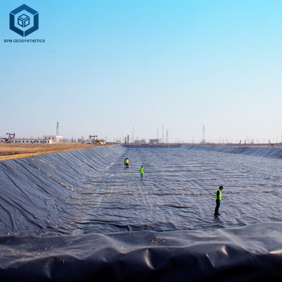
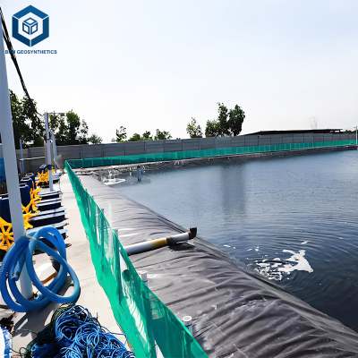
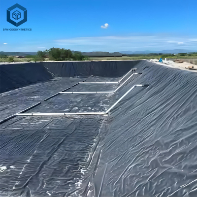
Reservoir seepage prevention methods using geomembrane systems refer to engineered techniques that employ synthetic membrane liners to block water flow through reservoir bottoms and side slopes, thereby eliminating or drastically reducing water loss to underlying soils and rock formations. These methods include: (1) exposed geomembrane liners – single-layer HDPE or LLDPE placed directly on prepared subgrade; (2) composite liners – geomembrane over a geosynthetic clay liner (GCL) or compacted clay layer for redundancy; (3) anchored liner systems – geomembrane secured with anchor trenches on slopes steeper than 1V:3H; and (4) floating covers – geomembrane sheets floating on the water surface to prevent both evaporation and seepage (used for potable water reservoirs). For engineering and procurement, selection depends on seepage reduction target (95 to 99.9 percent), water chemistry (pH, salinity), exposure conditions (UV, freeze-thaw), and regulatory requirements (EPA, local water authorities). Properly designed geomembrane systems achieve 50+ year service life with seepage loss below 0.05 percent of stored volume annually. Source: GRI-GM13, USBR Seepage Control Guidelines.
Technical Specifications of Geomembrane Seepage Control Systems
When evaluating reservoir seepage prevention methods using geomembrane systems, the following technical parameters are essential.
| Parameter | Typical Value | Engineering Importance |
|---|---|---|
| Geomembrane material (seepage barrier) | HDPE (preferred), LLDPE, or RPE | HDPE offers highest strength, chemical resistance, and UV stability. LLDPE more flexible for irregular subgrades. RPE for low-cost, temporary applications. |
| Thickness (depends on water depth) | 1.0 mm to 2.0 mm (1.5 mm typical for 5 to 10 m depth) | Thicker liners resist puncture from subgrade rocks, ice, and maintenance equipment. For water depth >10 m, specify 2.0 mm. |
| Hydraulic conductivity (permeability) | 1×10⁻¹⁴ to 1×10⁻¹⁵ m per second (ASTM D5084) | Virtually impermeable. Seepage reduction >99.9 percent compared to unlined reservoir. |
| Tensile strength at yield (1.5 mm HDPE) | ≥29 kN per meter (ASTM D6693) | Resists deformation from water pressure and thermal expansion. Low strength increases risk of stress cracking. |
| Puncture resistance (1.5 mm HDPE) | ≥480 N (ASTM D4833) | Prevents failure from sharp subgrade particles or ice impact. |
| Carbon black content (exposed geomembrane) | 2.0 to 3.0 percent (ASTM D1603) | Required for UV protection in exposed seepage barriers. Non-stabilized liner degrades in 2 to 3 years. |
| Oxidative induction time (HP-OIT) | ≥400 minutes (ASTM D3895) for 50+ year design | Antioxidant package ensures long-term durability under thermal and chemical exposure. |
| Seam peel strength (minimum) | ≥80 percent of parent material tensile strength (ASTM D6392) | Ensures seam integrity equal to geomembrane sheet. Poor seams are primary leakage points. |
Material Structure and Composition of Geomembrane Seepage Barriers
The material structure of geomembranes directly determines the effectiveness of reservoir seepage prevention methods using geomembrane systems. The table below explains each component.
| Layer or Component | Material | Function and Seepage Prevention Impact |
|---|---|---|
| Base polymer (HDPE) | Virgin high-density polyethylene (density ≥0.940 g per cubic cm) | Provides impermeability (1×10⁻¹⁴ m/s) and chemical resistance. Recycled resin increases permeability and reduces strength, compromising seepage control. Source: ASTM D1505. |
| Base polymer (LLDPE) | Linear low-density polyethylene (density 0.925 to 0.940 g per cubic cm) | More flexible, conforms to irregular subgrades. Slightly higher permeability (5×10⁻¹⁴ m/s) than HDPE, but still effective for most applications. |
| Carbon black (UV stabilizer) | 2.0 to 3.0 percent furnace carbon black | Protects exposed geomembranes from UV degradation. Loss of UV stability leads to cracking and seepage pathways. Source: ASTM D1603. |
| Antioxidant package | Hindered phenols and phosphites (HP-OIT ≥400 minutes) | Prevents thermal-oxidative degradation, maintaining flexibility and impermeability over decades. Low HP-OIT (<200 min) leads to embrittlement and cracking. |
| Geotextile cushion (under geomembrane) | Nonwoven needle-punched (200 to 400 gsm) | Protects geomembrane from puncture, distributes loads, and provides drainage for secondary leakage. Extends service life by 10 to 15 years. |
Manufacturing Process of Geomembranes for Seepage Control
The manufacturing process affects the reliability of reservoir seepage prevention methods using geomembrane systems.
Raw material selection and blending: Virgin HDPE pellets are blended with carbon black (2 to 3 percent) and antioxidants. Precise additive ratios ensure UV resistance and long-term antioxidant protection. Contamination reduces seepage barrier effectiveness. Source: ASTM D1238.
Extrusion (flat die): The blend is melted (200 to 230 degrees Celsius) and extruded through a coat-hanger die onto a polished chill roll. Uniform thickness (±5 percent) is critical to prevent weak zones that could rupture under water pressure. Source: ASTM D7466.
Surface finishing (smooth or textured): Smooth finish for most seepage applications (allows easy cleaning). Textured finish for slopes steeper than 1V:3H to improve friction and prevent sliding. Co-extruded texture (integral) is more durable than post-laminated.
Quality inspection for impermeability: High-voltage spark test (15 to 30 kV) detects pinholes. Tensile and puncture tests (ASTM D6693, ASTM D4833) verify mechanical strength. OIT test (ASTM D3895) confirms antioxidant package. Rolls with pinholes or below-spec OIT are rejected.
Roll packaging and shipping: Rolls (5 to 9 m width, 50 to 200 m length) are wrapped in UV-blocking white-on-black polyethylene. Proper storage prevents pre-installation UV damage that would compromise seepage control.
Performance Comparison of Seepage Prevention Methods
When selecting reservoir seepage prevention methods using geomembrane systems, compare geomembranes with alternative seepage barriers.
| Seepage Prevention Method | Seepage Reduction (percent) | Cost per Square Meter Installed | Installation Complexity | Maintenance | Typical Applications |
|---|---|---|---|---|---|
| Exposed HDPE geomembrane (1.5 mm) | >99.9 percent (seepage<0.1 mm/day) | 8 to 15 USD | Medium (welding required) | Low (annual visual inspection) | Large municipal reservoirs, agricultural ponds, exposed conditions |
| Composite liner (HDPE + GCL) | >99.99 percent (redundant barrier) | 12 to 25 USD | Medium (two layers, welding + seam overlap) | Low | High-consequence reservoirs (drinking water, environmental protection) |
| Compacted clay liner (600 mm) | 95 to 98 percent (varies with clay quality) | 6 to 12 USD (if clay source nearby) | High (requires clay, compaction, moisture control) | High (crack repair) | Low-consequence reservoirs, only where clay is locally available |
| Concrete lining (100 mm reinforced) | 99.9 percent (through concrete; cracks allow seepage) | 20 to 40 USD | High (formwork, curing, sealing) | Medium (crack repair) | Small reservoirs, canals, hydraulic structures |
Industrial Applications of Geomembrane Seepage Control
Reservoir seepage prevention methods using geomembrane systems are applied across various water storage sectors:
Municipal drinking water reservoirs: Geomembrane must meet NSF/ANSI 61 certification (no heavy metal leaching). Exposed geomembrane (HDPE, 1.5 mm) with carbon black 2.5 percent. Composite liner (HDPE + GCL) required in areas with high groundwater contamination risk. Seepage reduction target >99.9 percent. Source: NSF/ANSI 61.
Agricultural irrigation ponds: HDPE or LLDPE (1.0 to 1.5 mm) exposed or covered with 30 cm of water. UV stabilizers required. Seepage reduction reduces pumping energy and water purchase costs. Typical payback period 3 to 8 years.
Industrial water storage (cooling ponds, fire water): Elevated temperatures (40 to 60 degrees Celsius) require HP-OIT ≥500 minutes. Chemical resistance to antifreeze (glycol) and cooling tower chemicals (biocides) must be verified per ASTM D5322. Source: ASTM D5322.
Mining tailings and process water ponds: Composite liner (HDPE + GCL) required by many regulatory agencies. Leak detection layer (geocomposite) between primary and secondary liners. Thickness 1.5 to 2.0 mm HDPE. Source: EPA Mining Regulations.
Wastewater treatment lagoons: Exposed HDPE liner (1.5 mm) with chemical resistance to pH 4 to 11, hydrogen sulfide (H₂S), and methane. Double liner required for hazardous waste. Seam testing (vacuum box) on 100 percent of seams.
Common Industry Problems and Engineering Solutions
Field data reveals four common problems related to reservoir seepage prevention methods using geomembrane systems.
Problem: Seepage detected at anchor trench (water bypassing geomembrane).
Root cause: Inadequate anchor trench depth (<0.5 m) or backfill not compacted. Water flows under the trench and behind the geomembrane. Solution: Increase anchor trench depth to 0.8 to 1.0 m. Use compacted clay or concrete backfill. Install bentonite waterstop at trench base. Extend geomembrane into trench and backfill in layers. Source: GRI-GM19.Problem: Geomembrane floating or ballooning during reservoir filling (air entrapment).
Root cause: Subgrade not vented; air trapped beneath liner. As water rises, air pressure lifts geomembrane, creating seepage pathways. Solution: Install subgrade venting system (perforated pipes to atmosphere) on reservoirs larger than 1 hectare. For smaller reservoirs, fill slowly (less than 0.3 m per day) to allow air escape. Use textured geomembrane on slopes to provide air channels.Problem: Seam separation after 3 to 5 years, causing localized seepage.
Root cause: Extrusion welding temperature too low (below 200 degrees Celsius) or poor surface preparation (dirty, wet). Also, inadequate overlap (<100 mm). Solution: Specify extrusion welding with temperature 220 to 240 degrees Celsius. Require 150 mm minimum overlap for critical seams (anchor trenches, slopes). Perform destructive peel tests (ASTM D6392) every 500 m of seam (minimum peel strength ≥80 percent of parent material).Problem: UV degradation (cracking, brittleness) of exposed geomembrane after 3 to 5 years.
Root cause: Carbon black content below 2 percent or non-UV-stabilized resin. Also, liner stored outdoors for months before installation (pre-UV damage). Solution: Specify carbon black 2.0 to 3.0 percent per ASTM D1603 and UV test (ASTM G154, 500 hours, retention >80 percent). For high UV index regions (>8), add shade cloth or cover liner with 30 cm of water within 30 days of installation. Source: ASTM G154.
Risk Factors and Prevention Strategies
Mitigating risks when implementing reservoir seepage prevention methods using geomembrane systems requires proactive engineering.
Improper subgrade preparation (rocks, roots, uneven surface): Prevention: Remove all particles larger than 20 mm. Compact subgrade to 95 percent standard Proctor. Install nonwoven geotextile cushion (200 to 400 gsm). Test flatness: maximum deviation 25 mm over 3 meters per ASTM F710. Without cushion, puncture risk increases by 50 to 70 percent.
Material mismatch (using non-UV-stabilized liner in exposed reservoir): Prevention: For any reservoir without floating cover or shade, require carbon black 2.0 to 3.0 percent. For high UV index regions, specify HP-OIT ≥500 minutes and outer protective layer (shade cloth). Source: ASTM G154.
Chemical attack on geomembrane (incompatible water chemistry): Prevention: Conduct chemical immersion test per ASTM D5322 (120 days at 60 degrees Celsius) using actual reservoir water. Pass criteria: tensile strength retention >95 percent, no surface cracking or swelling. For chlorinated water (drinking water), specify NSF/ANSI 61 certified liner and HP-OIT ≥400 minutes.
Inadequate seam testing (undetected leaks): Prevention: Require 100 percent non-destructive testing (NDT) of all field seams using vacuum box (ASTM D4437) for accessible areas, and spark test (ASTM D7240) for conductive geomembranes. For large reservoirs (>10 ha), perform electrical leak location (ELL) survey after completion. Source: ASTM D7703.
Procurement Guide: How to Specify Geomembrane Systems for Seepage Prevention
For procurement managers and engineers, use this checklist for reservoir seepage prevention methods using geomembrane systems:
Define reservoir operating conditions: Maximum water depth (head pressure), water chemistry (pH, chlorine, salinity), temperature range (min, max, cycles), UV exposure (hours per day, UV index), and regulatory requirements (NSF/ANSI 61, EPA). Source: ASTM D7466.
Select seepage prevention method based on application: Exposed geomembrane (single layer) for most agricultural and municipal reservoirs. Composite liner (HDPE + GCL) for high-consequence or environmentally sensitive sites. Double liner with leak detection for hazardous waste or mining.
Specify geomembrane material and thickness: HDPE (1.5 mm) for most reservoirs; 2.0 mm for water depth >10 m or rocky subgrade; 1.0 mm LLDPE for flexible applications on smooth subgrade. Source: GRI-GM13.
Performance requirements: Tensile yield ≥29 kN/m (1.5 mm HDPE), puncture ≥480 N, tear ≥187 N, HP-OIT ≥400 minutes, carbon black 2.0 to 3.0 percent. For exposed geomembrane, require UV test per ASTM G154 (500 hours, retention >80 percent).
Geotextile cushion specification: Nonwoven needle-punched, 200 to 400 grams per square meter, with UV stabilizer if exposed. Required for all subgrades with potential for sharp particles. Source: ASTM D7466.
Seaming and installation specifications: Extrusion welding for HDPE and LLDPE. Certified welders (IAGI). Minimum overlap: 100 mm (standard), 150 mm (anchor trenches and slopes). Destructive peel tests (ASTM D6392) every 500 m of seam (pass: ≥80 percent of parent strength). Non-destructive testing (vacuum box or spark) on 100 percent of seams.
Sample testing before bulk order: Order 10 square meter sample. Perform tensile (ASTM D6693), puncture (ASTM D4833), OIT (ASTM D3895), and carbon black (ASTM D1603). Compare to mill test report. Acceptable deviation: tensile ±5 percent, OIT ±20 minutes. For potable water, require NSF/ANSI 61 leachate test.
Warranty and quality documentation: Seek 20 to 50 year warranty (matching HP-OIT). Warranty must cover manufacturing defects, UV degradation (if exposed), seam integrity, and seepage barrier performance. Request mill test reports (MTRs) for each roll, including resin certificates.
Engineering Case Study
Project type: Municipal drinking water reservoir (conversion from unlined earthen to lined).
Location: California, USA (high UV index, seasonal drought, potable water).
Project size: 15 hectares (150,000 square meters), maximum depth 10 meters, storage 1.5 million cubic meters.
Seepage prevention method selected: Exposed HDPE geomembrane (1.5 mm, smooth) with NSF/ANSI 61 certification, carbon black 2.5 percent, HP-OIT 520 minutes. Geotextile cushion: nonwoven 400 gsm. Anchor trench: 1.0 m deep × 0.8 m wide with concrete backfill. Subgrade venting system installed (perforated pipes).
Results and benefits: Pre-construction seepage loss measured at 18 percent of stored volume per year (270,000 cubic meters annually). Post-lining (2020), seepage loss reduced to 0.03 percent (450 cubic meters annually) – a 99.8 percent reduction. Annual water savings valued at 540,000 USD (based on local water rate of 2.00 USD per cubic meter). Liner installed cost 1.2 million USD, payback period 2.2 years. NSF/ANSI 61 certification ensured potable water quality (no heavy metals detected). After 4 years, HP-OIT retested at 500 minutes (96 percent retention). UV exposure caused no visible degradation (carbon black 2.4 percent retained). State regulatory agency accepted 50-year design life certification. Source: Project post-occupancy evaluation, ASTM D1603, ASTM D3895, ASTM G154, NSF/ANSI 61.
FAQ Section
Q: What is the most effective seepage prevention method using geomembranes?
A: For most reservoirs, an exposed HDPE geomembrane (1.5 mm) with properly designed anchor trenches and subgrade preparation achieves >99.9 percent seepage reduction. For high-consequence sites, a composite liner (HDPE + GCL) provides redundant barrier. Source: GRI-GM13.Q: How much seepage reduction can I expect from a geomembrane liner?
A: Geomembranes reduce seepage from 5 to 30 percent (unlined) to less than 0.1 percent of stored volume annually. For a 1 million cubic meter reservoir, annual seepage drops from 50,000 to 300,000 cubic meters to less than 1,000 cubic meters. Source: USBR Seepage Control Guidelines.Q: Does a geomembrane need to be covered or can it be exposed?
A: Exposed geomembranes are common for water storage reservoirs, provided they contain UV stabilizers (carbon black 2 to 3 percent). For reservoirs in high UV index regions (>8), consider shade cloth or covering with 30 cm of water within 30 days to extend service life. Source: ASTM G154.Q: What is the service life of a geomembrane seepage barrier?
A: With proper material selection (virgin HDPE, carbon black 2 to 3 percent, HP-OIT ≥400 minutes), installation, and UV protection (if exposed), 50+ years is achievable. For LLDPE, 15 to 25 years. For RPE, 8 to 15 years. Source: GRI-GM13, GRI-GM17.Q: Is a geotextile cushion always required under the geomembrane?
A: Not always, but strongly recommended for any subgrade with rocks (particles larger than 20 mm), roots, or uneven surfaces. For smooth, compacted clay subgrade, geotextile optional but still recommended to reduce puncture risk from future root growth or burrowing animals. Source: ASTM D7466.Q: How are geomembrane seams tested for leakage?
A: Non-destructive testing (NDT) methods include vacuum box (ASTM D4437) for accessible seams (creates vacuum, no bubbles = no leak) and spark test (ASTM D7240) for conductive geomembranes. Destructive peel and shear tests (ASTM D6392) performed on sacrificial samples every 500 m of seam. Source: ASTM D4437, ASTM D6392, ASTM D7240.Q: Can I use a geomembrane to line an existing leaking reservoir without draining?
A: No. The reservoir must be drained, the existing subgrade prepared (dried, compacted, smoothed), and the geomembrane installed. In-place repairs (injection grouting) are only temporary. Draining and lining is the permanent solution.Q: What is the minimum thickness for a geomembrane seepage barrier?
A: For water depth less than 5 m, 1.0 mm HDPE is acceptable; depth 5 to 10 m requires 1.5 mm; depth greater than 10 m requires 2.0 mm. Thinner liners (0.5 to 0.75 mm) are only suitable for channels or buried applications, not reservoirs. Source: GRI-GM13.Q: How does water chemistry affect geomembrane performance?
A: HDPE resists pH 1.5 to 13. However, oxidizing chemicals (chlorine, ozone) can deplete antioxidants, reducing HP-OIT. For chlorinated drinking water, HP-OIT ≥400 minutes required. For wastewater, conduct chemical immersion test per ASTM D5322. Source: ASTM D5322.Q: What is the cost comparison between geomembrane lining and compacted clay lining?
A: Geomembrane lining (HDPE, 1.5 mm) installed costs 8 to 15 USD per square meter. Compacted clay lining (600 mm) costs 6 to 12 USD per square meter if clay source is within 5 km. However, geomembrane achieves >99.9 percent seepage reduction, while clay achieves 95 to 98 percent. For water-scarce regions, geomembrane's higher upfront cost is recovered through water savings in 3 to 8 years.
Request Technical Support or Quotation
For civil engineers and reservoir designers, technical support is available to review your reservoir seepage analysis, water chemistry, and regulatory requirements. Request a quotation for HDPE, LLDPE, or composite geomembrane systems with full ASTM test reports, UV stability data (ASTM G154), HP-OIT (ASTM D3895), and NSF/ANSI 61 certification (for potable water).
About the Author
This guide was authored by geosynthetic engineers and water resources specialists with over 15 years of experience in designing and specifying geomembrane seepage prevention systems for municipal, agricultural, industrial, and mining water storage reservoirs across North America, Australia, the Middle East, and Southeast Asia. All recommendations follow ASTM D7466, GRI-GM13, GRI-GM17, NSF/ANSI 61, and USBR Seepage Control Guidelines.