How to Install HDPE Geomembrane Step by Step: Engineering Guide
What is How to Install HDPE Geomembrane Step by Step?
How to install HDPE geomembrane step by step refers to the systematic engineering procedure for placing and welding high-density polyethylene liner sheets to create a continuous impermeable barrier for environmental containment. For civil engineers, EPC contractors, and procurement managers, understanding how to install HDPE geomembrane step by step is critical for ensuring liner integrity, regulatory compliance, and 50–100+ year design life. The installation process follows strict protocols per GRI GM17 and ASTM standards: subgrade preparation (removing stones > 12 mm, achieving flatness ≤ 2 mm/2m), panel layout (minimizing field seams), deployment (unrolling without damage), thermal welding (dual-track fusion for field seams, extrusion welding for patches), non-destructive testing (air channel, vacuum box, spark testing), and destructive testing (peel and shear per ASTM D6392). This guide provides engineering analysis of how to install HDPE geomembrane step by step: equipment requirements (welding machines, testing tools), quality control hold points, common installation errors, and acceptance criteria for landfill liners, mining heap leach pads, and pond liners.
Technical Specifications for HDPE Geomembrane Installation
The table below defines critical parameters for how to install HDPE geomembrane step by step per GRI GM17 and ASTM standards.
| Parameter | Required Value | Engineering Importance | |
|---|---|---|---|
| Subgrade Flatness (ASTM F710) | ≤ 2 mm per 2 m (≤ 3 mm per 3 m) | Prevents stress concentration and punctures. Critical first step in how to install HDPE geomembrane step by step.}, | |
| Subgrade Stones / Debris | Remove stones > 12 mm, all roots, sharp objects | Puncture prevention. Mandatory before liner placement.}, | |
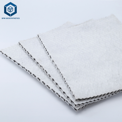
| Geotextile Cushion (if required) | Nonwoven, ≥ 300 g/m² (500 g/m² for sharp subgrade) | Protects geomembrane from subgrade punctures.}, | |
| Panel Overlap (field seams) | 75 – 100 mm for dual-track thermal weld | Sufficient material for welding and testing.}, | |
| Dual-Track Weld Temperature (HDPE) | 400 – 500°C (depending on thickness and speed) | Insufficient temperature → incomplete fusion; excessive → degradation.}, | |
| Dual-Track Weld Speed | 1.5 – 3.5 m/min (for 1.5 mm HDPE) | Speed must match temperature for proper fusion.}, | |
| Extrusion Weld Temperature | 200 – 240°C (for 1.5 mm HDPE) | For patch welding and detail work.}, | |
| Air Channel Test Pressure | 100 – 200 kPa (hold 2–5 minutes) | Pressure drop > 20% indicates seam defect.}, | |
| Destructive Test Frequency | 1 sample per 500 m of seam (minimum) | Peel strength ≥ 90% of parent; shear strength ≥ 75%.}, | |
| Ambient Temperature for Installation | -10°C to +40°C (avoid rain, snow, high wind) | Extreme conditions affect welding quality.}, |
Key takeaway: How to install HDPE geomembrane step by step requires strict subgrade preparation, proper welding parameters, and comprehensive seam testing (non-destructive + destructive).
Material Structure and Composition: How HDPE Construction Affects Installation
Understanding HDPE geomembrane properties helps in proper installation.
| Property | Typical Value | Installation Impact |
|---|---|---|
| Thickness | 1.0 – 2.5 mm | Thicker geomembranes require higher weld temperature and slower speed.}, |
| Density (ASTM D1505) | 0.940 – 0.960 g/cm³ | Higher density = stiffer material; requires careful panel deployment to avoid wrinkles.}, |
| Melt Flow Index (MFI) | 0.3 – 1.0 g/10 min | Low MFI (high molecular weight) welds well but requires precise temperature control.}, |
| Carbon Black Content | 2.0 – 3.0% | Affects UV resistance during temporary exposure before cover.}, |
| Surface Texture | Smooth or textured (single/double-sided) | Textured requires higher weld pressure and slower speed.}, |
Engineering insight: How to install HDPE geomembrane step by step must account for material thickness, texture, and ambient conditions — weld parameters are not universal.
Manufacturing Process: How HDPE Geomembrane Is Produced for Installation
Factory quality affects field installation success.
Resin compounding: Virgin PE100 resin + carbon black + antioxidants blended.
Extrusion: Flat die extrusion (200–220°C) → calendering rolls set thickness.
Cooling: Sheet passes over cooling rolls (40–60°C).
Surface texturing (optional): Embossing rolls create single or double-sided texture.
Roll winding: Geomembrane rolled onto steel cores. Roll width 5–10 m, length 50–200 m.
Packaging: UV-protective wrapping for shipping.
Procurement insight: For how to install HDPE geomembrane step by step, request roll dimension data (width, length, weight) and factory test reports (tensile, tear, puncture, PENT, OIT) before delivery.
Performance Comparison: HDPE vs. Other Liner Installation Complexity
Comparing installation requirements for different liner materials.
| Liner Type | Welding Required | Skill Level | Seam Testing | Installation Speed (m²/day/crew) | Typical Applications |
|---|---|---|---|---|---|
| HDPE Geomembrane | Yes (thermal welding) | High (certified welders) | Extensive (air channel, vacuum, destructive) | 2,000 – 5,000 | Landfill liners, mining, chemical containment}, |
| LLDPE Geomembrane | Yes (thermal welding) | High | Same as HDPE | 2,000 – 5,000 | Slopes, flexible applications}, |
| PVC Geomembrane | Yes (chemical or dielectric welding) | Medium | Moderate | 3,000 – 6,000 | Canals, decorative ponds}, |
| GCL (Geosynthetic Clay Liner) | No (overlaps only) | Low | None (visual inspection) | 5,000 – 10,000 | Landfill covers, secondary containment}, |
Conclusion: How to install HDPE geomembrane step by step requires skilled labor and extensive testing, unlike GCL which is simpler but has lower chemical resistance.
Industrial Applications of HDPE Geomembrane Installation
Different applications have specific installation requirements.
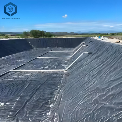
Landfill bottom liners: Requires double-track thermal welding, 100% non-destructive testing, and destructive samples every 500 m. Subgrade must be smooth and stone-free.
Landfill final covers: Similar to bottom liners, but may use thinner geomembrane (1.0 mm).
Mining heap leach pads: Requires textured geomembrane for slope stability. Welding on slopes requires additional safety measures.
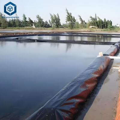
Wastewater treatment lagoons: Large panels reduce field seams. Extrusion welding for pipe penetrations.
Secondary containment (tank farms): Small areas with many penetrations (pipes, sumps). Requires detailed extrusion welding around fittings.
Common Industry Problems in How to Install HDPE Geomembrane Step by Step
Real-world failures from improper installation procedures.
Problem 1: Wrinkles causing stress cracking
Root cause: Improper panel deployment — tension not maintained, wrinkles not removed. Solution: During how to install HDPE geomembrane step by step, unroll panels with tensioning bars. Remove wrinkles by slitting and patching if necessary.
Problem 2: Seam failure from contamination (dust, moisture)
Root cause: Seam area not cleaned before welding. Dust or moisture prevents fusion. Solution: Clean seam area with isopropyl alcohol and lint-free cloth immediately before welding. This is a critical step in how to install HDPE geomembrane step by step.
Problem 3: Cold weld (incomplete fusion) from low temperature
Root cause: Weld temperature too low or speed too fast. Peel test shows adhesive failure. Solution: Calibrate welding machine at start of each shift. Perform peel test on sample strip before production welding.
Problem 4: Geomembrane puncture from subgrade stones
Root cause: Subgrade preparation inadequate — stones > 12 mm not removed. Solution: Proof-roll subgrade, remove all stones > 12 mm. Install geotextile cushion (≥ 300 g/m²). Perform electrical leak location survey after installation.

Risk Factors and Prevention Strategies for HDPE Geomembrane Installation
Risk: Welding in cold weather (< 0°C): Reduced heat transfer, brittle material. Mitigation: Use heated enclosures or preheat weld area. Do not weld below -10°C.
Risk: Welding in wind (> 25 km/h): Rapid cooling of weld zone, contamination from dust. Mitigation: Use wind screens. Stop welding in high winds.
Risk: Inadequate destructive testing frequency: Undetected seam defects. Mitigation: Minimum 1 destructive sample per 500 m of seam per weld type. For critical applications, 1 per 250 m.
Risk: No non-destructive testing of all seams: Air channel test only for dual-track welds. Single-track or extrusion welds require vacuum box or spark testing. Mitigation: Test 100% of seams with appropriate method.
Procurement Guide: How to Specify HDPE Geomembrane Installation Requirements
Follow this 8-step checklist for B2B purchasing decisions.
Require certified installation crew: IAGI or GRI certified welders and installers. Experience verification.
Specify subgrade preparation: Remove stones > 12 mm, flatness ≤ 2 mm/2m. Include hold point for inspection before liner placement.
Require geotextile cushion: Specify nonwoven geotextile mass (≥ 300 g/m², 500 g/m² for sharp subgrade).
Specify welding equipment: Dual-track thermal welder for field seams; extrusion welder for patches. Require calibration records.
Define seam testing protocol: Non-destructive: 100% air channel testing (dual-track) + vacuum box for extrusion welds. Destructive: 1 sample per 500 m of seam.
Require destructive test acceptance criteria: Peel ≥ 90% parent strength, shear ≥ 75% parent strength, with ductile failure (no brittle fracture).
Order installation mockup: Install 100 m² test section. Perform all seam tests. Document weld parameters.
Specify post-installation leak detection: Electrical leak location survey (ASTM D7002) before covering.
Engineering Case Study: How to Install HDPE Geomembrane Step by Step in Landfill Liner
Project type: Municipal solid waste landfill bottom liner (1.5 mm HDPE).
Location: Midwest USA.
Project size: 100,000 m².
Installation steps:
1. Subgrade preparation: Removed stones > 12 mm, flatness 2 mm/2m.
2. Geotextile cushion: 300 g/m² nonwoven.
3. Panel deployment: 7 m × 100 m rolls, deployed with tensioning bars. Wrinkles removed.
4. Seam welding: Dual-track thermal welder, temperature 450°C, speed 2.5 m/min.
5. Seam testing: Air channel (200 kPa, 3 min hold) on all seams; destructive samples every 250 m (peel 520 N, shear 480 N).
6. Repairs: Extrusion welded patches for 3 small punctures.
7. Electrical leak location: Detected 2 additional leaks; repaired.
Results: Installation completed in 6 weeks. Passed regulatory inspection. No leaks after 5 years. This case demonstrates that how to install HDPE geomembrane step by step with proper QA/QC prevents failures.
Frequently Asked Questions: How to Install HDPE Geomembrane Step by Step
Q1: What is the first step in how to install HDPE geomembrane step by step?
Subgrade preparation: Remove all stones > 12 mm, roots, and debris. Achieve flatness ≤ 2 mm per 2 m (ASTM F710). This is the most critical step.
Q2: What type of welding is used for HDPE geomembrane field seams?
Dual-track thermal fusion welding (hot wedge) is standard for field seams. Extrusion welding is used for patches, repairs, and detail work around penetrations.
Q3: How are HDPE geomembrane seams tested?
Non-destructive testing: air channel test for dual-track welds (pressurize to 100–200 kPa, hold 2–5 min). Vacuum box or spark testing for extrusion welds. Destructive testing: peel and shear per ASTM D6392 (1 sample per 500 m of seam).
Q4: What is the minimum overlap for HDPE geomembrane seams?
75–100 mm for dual-track thermal welds. The two weld tracks are typically 10–15 mm wide with a 10–15 mm air channel between them.
Q5: Can HDPE geomembrane be installed in cold weather?
Yes, down to -10°C with proper precautions. Weld temperature must be increased (5–10°C higher), speed reduced. Use heated enclosures for welding equipment. Acclimate material to site temperature.
Q6: How are wrinkles removed during HDPE geomembrane installation?
Tension the panel during deployment using tensioning bars. For existing wrinkles, slit the geomembrane along the wrinkle, flatten, and patch with extrusion weld. Do not cover wrinkles — they will become stress cracking sites.
Q7: What is the acceptable peel strength for HDPE geomembrane seams?
≥ 90% of parent sheet strength. For 1.5 mm HDPE (parent ~320 N/25 mm), peel strength should be ≥ 288 N/25 mm with ductile failure (no brittle fracture).
Q8: How long does it take to install HDPE geomembrane?
A typical crew (4–6 people) installs 2,000–5,000 m² per day depending on site conditions, panel size, and seam length. A 100,000 m² landfill liner takes 4–8 weeks.
Q9: What is the role of geotextile in HDPE geomembrane installation?
Geotextile (nonwoven) provides puncture protection from subgrade stones, separation from soil, and drainage (filtration). It is placed directly under the geomembrane.
Q10: What is electrical leak location and when is it performed?
Electrical leak location (ASTM D7002) detects pinholes and small punctures in installed geomembrane. It is performed after all seams are welded and before cover soil placement. It is the final QA/QC step in how to install HDPE geomembrane step by step.
Request Technical Support or Quotation for HDPE Geomembrane Installation
For project-specific installation specifications, QA/QC plans, or contractor training, our technical team is available.
Request a quotation – Provide thickness, area, application type, and site conditions.
Request engineering samples – Receive HDPE geomembrane samples with welding parameters and test reports.
Download technical specifications – GRI GM17 installation guide, seam testing protocol, and QA/QC checklist.
Contact technical support – Subgrade assessment, welding parameter optimization, and installation QA/QC support.
About the Author
This guide on how to install HDPE geomembrane step by step was written by Dipl.-Ing. Hendrik Voss, a civil engineer with 19 years of experience in geosynthetics and liner installation. He has supervised over 2 million m² of HDPE geomembrane installation across Europe, North America, South America, and Asia, specializing in welding QA/QC, seam testing, and failure investigation for landfill, mining, and water containment projects. He is a certified IAGI welding inspector and has trained over 300 geomembrane installation personnel. His work is referenced in GRI and ASTM D35 committee discussions on geomembrane installation standards.