HDPE Geomembrane Installation Guide
Properly understanding the guidelines for HDPE geomembrane installation is of great significance: it ensures the integrity and effectiveness of the seepage prevention system, eliminates the risk of leakage caused by improper construction at the source, and protects the safety of soil and groundwater; at the same time, standardized processes can extend the life of the project and reduce later maintenance costs. It is a fundamental prerequisite for achieving design standards and passing quality acceptance, and is directly related to the implementation of project safety and environmental responsibility.
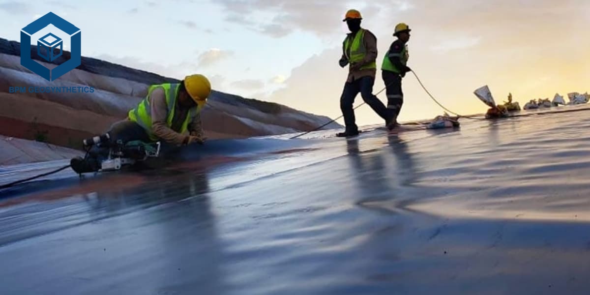
1. Step 1: Pre-Construction Preparation
Adequate technical and material preparation before commencement is fundamental to success.
1.1 Qualification Review:
Ensure the installation team possesses relevant certifications (such as IAGI certification) and extensive installation experience. The project manager and welding technicians should hold valid qualifications.
1.2 Scheme Approval:
The construction unit must submit an installation plan and membrane layout diagram in advance. Construction can only commence after review and approval. The layout diagram should minimize weld seams and clearly define the treatment methods for critical locations such as anchor trenches and slope toes.
1.3 Material Acceptance:
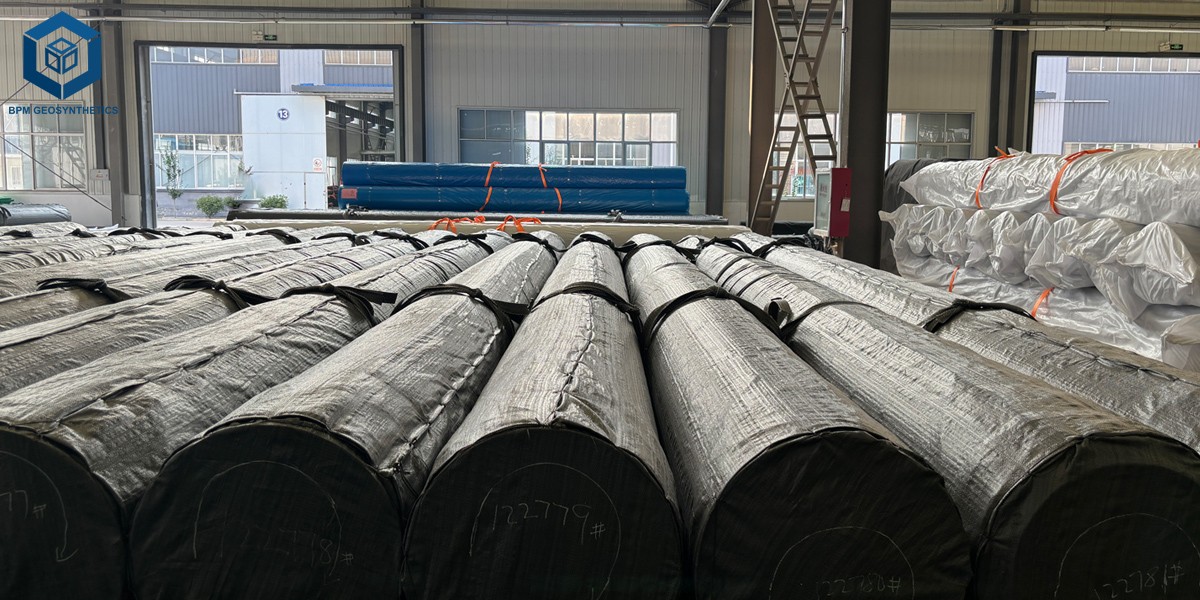
Upon arrival, materials must be verified against their factory certificates of conformity and quality inspection reports. The project engineer will typically take samples for archiving and inspect the membrane surface for damage such as bubbles and holes.
1.4 Environmental Restrictions:
Construction is strictly prohibited in rainy, snowy, or windy conditions (e.g., exceeding 20 mph). Extremely low or high temperatures (membrane surface temperature below 0°C or above 70°C) will also affect welding quality and require special care.
2. Step 2: Subgrade Preparation
Foundation treatment is a prerequisite for geomembrane laying. A flat and firm foundation is the fundamental guarantee against membrane damage and to ensure seepage prevention.
2.1 Foundation Surface Requirements:
The foundation surface must be flat, firm, and clean, thoroughly removing stones, tree roots, glass shards, and all sharp objects. The surface should not have significant unevenness, and the compaction degree should meet design requirements (usually not less than 95%). The surface in contact with the membrane should preferably be a densely compacted layer of fine soil, fine sand, or concrete.
2.2 Slope Design:
The foundation should have an appropriate drainage slope (generally not less than 2%) to avoid water accumulation. The slope should be smoothed, and internal and external corners should be rounded with a radius not less than 0.5m.
2.3 Acceptance and Protection:
Before laying each area, the installer and the owner's representative should jointly inspect and issue a written acceptance document. After acceptance, the geomembrane should be laid as soon as possible to prevent the foundation from being eroded by rainwater, cracked by drying, or subject to secondary pollution. It is recommended to use a "rolling + supplementary compaction" process to detect weak points, and any "soft points" found should be reworked promptly.
2.4 Subbase layer (optional):
For rock foundations or areas with a risk of sharp objects, a geotextile cushioning layer can be laid under the geomembrane to reduce the risk of the membrane being punctured.
3. Step 3: HDPE Geomembrane Liner Placement
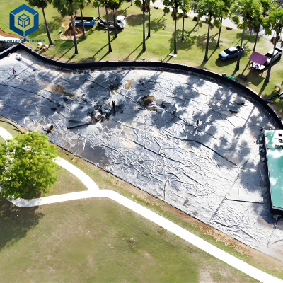
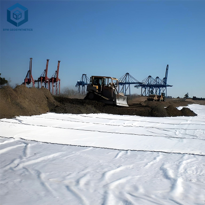
Laying is the process of placing geomembrane material onto the foundation according to the designed layout. The details of this operation directly affect the subsequent welding quality and the project's lifespan.
3.1 HDPE Geomembrane Laying Principles:
Follow the principle of "laying and welding on the same day," and the geomembrane liner should not be exposed to air for more than 30 days. On slopes, the geomembrane should be laid in the direction of the slope (i.e., the weld direction is parallel to the maximum slope line). Horizontal welds are strictly prohibited to prevent tensile failure of the welds due to the membrane's own weight or thermal expansion and contraction. Generally, no welds should be placed within 1.5m of the slope crest or stress concentration areas.
3.2 Overlap and Relaxation:
The overlap width between two adjacent membrane sheets should not be less than 100mm (4 inches). A 1%~2% relaxation should be allowed during laying to allow the membrane to naturally adhere in a wavy shape and avoid suspension, preventing tearing due to thermal expansion and contraction or foundation settlement.
3.3 Temporary Fixation and Wind Protection:
Immediately after laying, sandbags should be used to weigh down the edges and seams of the membrane, spaced 2-5 meters apart, with each sandbag weighing 20-40 kg. The sandbags should be made of fine, dense material to prevent fine soil from leaking out and contaminating the membrane surface. Anchoring trenches should be backfilled as soon as possible after the membrane is positioned to prevent slippage due to temperature changes.
3.4 Finished Product Protection:
After laying, walking on the membrane surface and handling tools should be minimized. All construction personnel must not wear shoes with spikes or high heels on the membrane, and smoking is strictly prohibited on the membrane surface. Objects that could damage the membrane must not be placed on it.
3.5 Slope Laying Points:
For smooth/rough double-sided membranes, the smooth side should face down in contact with the underlayment (for easy position adjustment), and the rough side should face up (to provide an anti-slip working surface). The anchoring trench dimensions are generally 0.4-1.0 m wide and 0.4-1.0 m deep, depending on the design specifications.
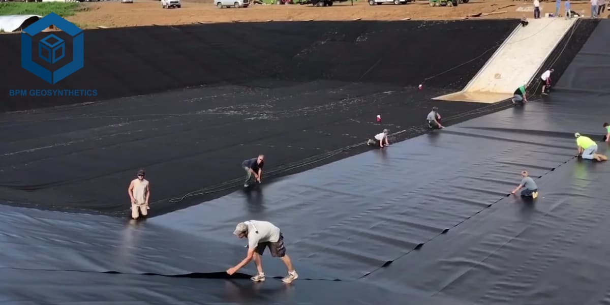
4. Step 4: HDPE Geomembrane Installation Field Seaming
Welding is the most critical process in geomembrane construction, and its quality directly determines the overall performance of the seepage prevention system. HDPE geomembrane welding mainly employs two processes: double-track fusion welding and extrusion welding.
4.1 Double-track Fusion Welding
Double-track fusion welding uses automated welding equipment to travel along the overlap area of two membrane sheets, forming two parallel, sealed weld seams with a hollow channel in the middle.
4.1.1 Applications:
Used for most straight and long weld seams, such as large-area site bottom and slope connections. This method has the advantages of fast welding speed and uniform and stable quality.
4.1.2 Operating Procedure:
- Pre-welding cleaning: The joint area should be dry, clean, and free of oil, mud, sand, standing water (including dew), and other debris.
- Equipment debugging: Adjust the welding machine's temperature, pressure, and travel speed according to the air temperature and material properties. Generally, the welding machine temperature is controlled above 200℃.
- Trial Welding: Before welding begins each day, a trial weld must be performed using a sample identical to the final material. On-site peel and shear tests must be conducted to confirm that the parameters are within acceptable limits before formal welding can commence. The recommended sample size is 0.9mm × 0.3mm, with an overlap width of no less than 10cm.
- Formal Welding: After the two geomembrane sheets are overlapped and laid flat, they are fed into the welding machine, and welding is initiated. During the welding process, the machine's operation must be continuously monitored, and fine adjustments made as needed.
- Weld Requirements: The weld should be smooth, clear, and transparent, without any incomplete welds, missed welds, or skipped welds.
4.2 Extrusion Welding
Extrusion welding is a welding method where a hot-melt welding rod (of the same material as the base material) is forced into the overlap or repair area using a handheld welding torch, forming a single-pass weld.
4.2.1 Applications:
Primarily used for repairing damage, handling T-joints, repairing defects, and in corners and irregular areas inaccessible to dual-rail welding machines.
4.2.2 Key Requirements:
The welding rod should have the same base resin and material properties as the geomembrane base material.
The welding surface should be ground to remove the oxide layer and kept clean and dry.
During welding, pay attention to controlling the torch angle and feed rate to ensure the molten material fully fuses. Do not wipe high-temperature areas directly with your hands.
The extrusion welding machine's slider should be replaced promptly when severely worn to avoid damaging the film surface.
4.3 Joint Design
4.3.1 T-joint treatment:
Adjacent welds should be staggered as much as possible. The joints formed between film blocks should be T-shaped, minimizing cross-shaped welds. T-joints and intersections of longitudinal and transverse welds should be reinforced using an extrusion welding machine.
4.3.2 Long-distance splicing:
When the film length is insufficient and splicing is necessary, weld the transverse welds first, then the longitudinal welds. The spacing between transverse welds should be greater than 50cm, forming a T-shape; cross-shaped intersections are strictly prohibited.
4.3.3 Power requirements:
The welding equipment should be powered by a generator with good voltage stability. When using local power, a voltage regulator must be provided to ensure stable welding parameters.
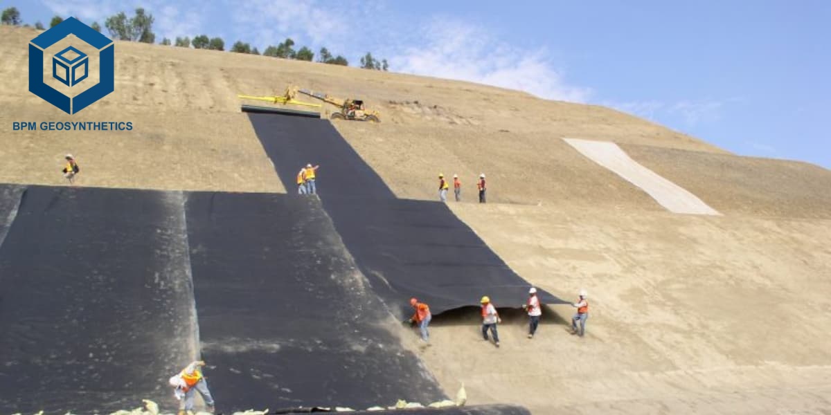
Step 5: HDPE Geomembrane Installation Quality Control & Repair
Rigorous quality inspection is essential to ensure a flawless project.
5.1 Non-Destructive Testing (NDT):
5.1.1 Double-Rail Welds:
Use a pressure test. Insert a needle into the cavity of the double-rail weld, apply the specified pressure (e.g., 25-30 psi), close the valve, and observe if the pressure stabilizes to determine the overall weld seal.
5.1.2 Compression Welds/Repair Points:
Use a vacuum chamber test. Spray soapy water onto the weld, cover it with a vacuum chamber, and evacuate the air. Observe through the transparent top cover for bubbles; the presence of bubbles indicates a leak.
5.2 Destructive Testing (DT):
Take samples from the weld at regular intervals (e.g., every 500 feet or per welding machine per shift) and send them to a laboratory for shear and peel strength testing to ensure the weld strength meets standards.
5.3 Repair Procedure:
For any detected damage or leaks, patches of the same material must be used for repair. Patches should be cut into round or oval shapes, with edges cleaned and polished, then firmly welded using a pressure welding gun. Finally, a non-destructive testing process must be performed again.
A qualified HDPE geomembrane installation project is far more than simply "laying plastic sheeting." It encompasses a comprehensive application of materials science, soil mechanics, and welding technology. Strictly adhering to the above steps is not only about following regulations but also about taking responsibility for project safety and the environment.
For reliable performance and consistent quality, we recommend The Best Project Material Co., Ltd.(BPM Geosynthetics) geomembrane solutions.