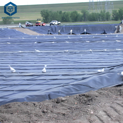
Geomembrane bubble formation under liner
Geomembrane bubble formation under liner refers to the development of air, gas, or vapor pockets trapped beneath a geomembrane barrier after installation. These bubbles can occur due to trapped moisture, gas generation from subgrade materials, thermal expansion, or inadequate venting systems. If uncontrolled, bubble formation may create liner stress, reduce contact with the subgrade, and compromise long-term containment performance in landfill, mining, and water infrastructure projects.
Technical Parameters and Engineering Specifications
Proper control of geomembrane bubble formation under liner requires strict adherence to material specifications, installation procedures, and subgrade preparation standards.
| Parameter | Typical Range | Engineering Notes |
|---|---|---|
| Geomembrane Thickness | 1.0 – 3.0 mm | Thicker liners reduce deformation caused by trapped gas |
| Material Type | HDPE / LLDPE | HDPE commonly used for landfill and mining liners |
| Subgrade Moisture Content | < 8% | High moisture increases vapor pressure |
| Installation Temperature | 5°C – 40°C | High temperature differences increase gas expansion |
| Gas Vent Spacing | 10 – 30 m | Used in landfill caps or biogas-producing layers |
| Welding Method | Double-track extrusion or hot wedge | Allows pressure testing for seam quality |
Structure and Material Composition
Typical containment systems designed to prevent geomembrane bubble formation under liner consist of multiple engineered layers.
Protective Layer – geotextile cushion preventing puncture
Geomembrane Liner – primary impermeable barrier
Drainage Layer – sand or geonet allowing gas or liquid movement
Gas Vent System – perforated pipes or vent stacks
Prepared Subgrade – compacted soil foundation
Moisture Control Layer – prevents vapor migration
The presence or absence of drainage and venting layers directly influences the risk of geomembrane bubble formation under liner conditions.
Manufacturing Process of Geomembrane Liners
Industrial production of geomembranes follows standardized extrusion processes to ensure uniform thickness and mechanical stability.
1. Raw Material Preparation
High-density polyethylene resin blended with carbon black, antioxidants, and stabilizers.
2. Extrusion Melting
Polymer pellets are melted in large extrusion systems at controlled temperatures (180–240°C).
3. Sheet Forming
The molten polymer passes through a flat die to form continuous sheets.
4. Calendering and Thickness Control
Rollers maintain uniform thickness and smooth surfaces.
5. Cooling and Stress Relief
Gradual cooling prevents internal stresses that could amplify deformation if geomembrane bubble formation under liner occurs.
6. Quality Testing
Tensile strength
Puncture resistance
Environmental stress crack resistance
Carbon black dispersion
Industry Material Comparison
| Material | Permeability | Resistance to Gas Pressure | Typical Application |
|---|---|---|---|
| HDPE Geomembrane | Very Low | High | Landfills, mining ponds |
| LLDPE Geomembrane | Low | Medium | Flexible containment systems |
| Clay Liner | Moderate | Low | Traditional environmental barriers |
| PVC Membrane | Low | Medium | Water reservoirs |
Application Scenarios
Understanding geomembrane bubble formation under liner is critical in projects where gas generation or vapor pressure is expected.
Municipal landfill base liners
Mining tailings storage facilities
Wastewater treatment lagoons
Industrial evaporation ponds
Agricultural water reservoirs
Biogas containment systems
Typical users include EPC contractors, environmental engineering firms, infrastructure developers, and international geomembrane distributors.

Core Problems and Engineering Solutions
1. Trapped Moisture in Subgrade
Moisture evaporates under sunlight and generates vapor pressure beneath the liner.
Solution: Ensure subgrade drying and install drainage layers.
2. Biological Gas Generation
Organic materials decompose and release methane or other gases.
Solution: Install gas venting systems and perforated pipe networks.
3. Thermal Expansion
Temperature differences cause expansion and contraction, amplifying trapped gas pockets.
Solution: Use flexible liner anchoring systems and temperature-controlled installation schedules.
4. Inadequate Subgrade Preparation
Uneven surfaces create voids where air can accumulate.
Solution: Perform precise grading, compaction, and surface smoothing.
Risk Warnings and Prevention Strategies
Never install geomembrane liners over wet or frozen soil
Avoid installation during rapid temperature fluctuations
Provide gas venting in waste containment applications
Perform vacuum or pressure testing on welded seams
Monitor bubble formation during the first thermal cycle
Ignoring geomembrane bubble formation under liner conditions may lead to liner uplift, seam stress, and long-term leakage risks.
Procurement and Selection Guide
Determine liner thickness based on containment risk level
Analyze subgrade moisture and gas generation potential
Specify HDPE material standards (ASTM / GRI)
Verify welding method and field testing procedures
Confirm drainage or vent layer design
Review manufacturer quality certifications
Request sample sheets for laboratory testing
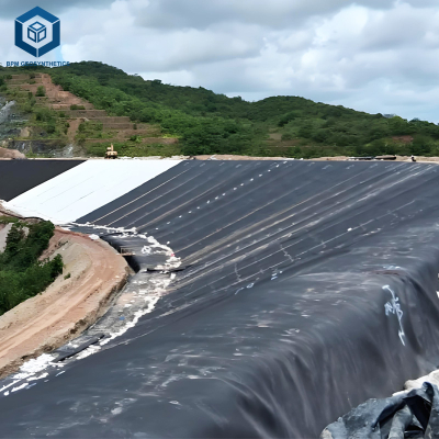
Engineering Case Example
In a mining tailings storage project in Southeast Asia, engineers observed early geomembrane bubble formation under liner across several sections of a 200,000 m² containment basin.
Investigation revealed that residual organic soil beneath the liner produced gas after flooding. Engineers installed a geonet drainage layer and a series of gas vent stacks every 20 meters.
After the redesign, bubble formation was eliminated and the containment system maintained full contact with the subgrade, ensuring long-term environmental protection.
FAQ – Geomembrane Bubble Formation Under Liner
1. What causes geomembrane bubble formation under liner?
Trapped air, vapor pressure, biological gas generation, or thermal expansion.
2. Are bubbles under geomembrane dangerous?
Yes, they can increase stress on seams and reduce liner stability.
3. Can bubble formation be prevented?
Proper subgrade preparation and gas vent systems greatly reduce risk.
4. Which geomembrane material performs best?
HDPE geomembrane is widely preferred for high-pressure containment.
5. Does temperature affect bubble formation?
Yes, temperature increases vapor pressure beneath liners.
6. Should drainage layers always be installed?
They are strongly recommended in landfill and mining environments.
7. How are bubbles detected during inspection?
Visual inspection and surface deformation monitoring.
8. What spacing is typical for gas vents?
Usually between 10 and 30 meters depending on project design.
9. Can bubbles damage welded seams?
Excess pressure may cause seam stress or failure.
10. Are geomembrane bubbles repairable?
Yes, controlled venting or localized liner adjustments can resolve the issue.
Request Technical Documentation or Quotation
For engineering specifications, installation guidance, or pricing information related to geomembrane systems designed to prevent geomembrane bubble formation under liner, procurement teams and EPC contractors may request:
Technical data sheets
Material samples for testing
Project design consultation
International supply quotations
Author Expertise and Industry Authority
This article was prepared by engineering professionals with extensive experience in geomembrane manufacturing, environmental containment systems, and large-scale infrastructure projects. The technical guidance reflects industry standards used by EPC contractors, landfill engineers, and international geomembrane suppliers.