Which Geomembrane for High Groundwater Level Site
Which geomembrane for high groundwater level site refers to selecting a geomembrane liner system engineered to resist hydrostatic uplift pressure, prevent seepage, and maintain long-term structural integrity in locations where groundwater exerts continuous upward force on containment structures.
Technical Parameters & Specifications
When evaluating which geomembrane for high groundwater level site conditions, the design must consider uplift pressure, tensile strength, puncture resistance, and seam integrity in accordance with GRI GM13 and relevant ASTM standards.
| Parameter | Recommended Value | Test Standard |
|---|---|---|
| Thickness | 1.5 mm – 2.5 mm | ASTM D5199 |
| Density (HDPE) | ≥ 0.94 g/cm³ | ASTM D1505 |
| Tensile Strength at Yield (1.5 mm) | ≥ 22 kN/m | ASTM D6693 |
| Puncture Resistance | ≥ 480 N (1.5 mm) | ASTM D4833 |
| Hydrostatic Resistance | No leakage | ASTM D5385 |
| Standard OIT | ≥ 100 min | ASTM D3895 |
| Seam Peel Strength | Film tear bond | ASTM D6392 |
For high groundwater level sites, minimum 1.5 mm HDPE geomembrane is commonly specified, with thicker sections required where uplift exceeds design assumptions.
Structure & Material Composition
Recommended System Configuration
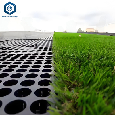
Compacted subgrade with drainage blanket
Geotextile cushion layer (300–600 g/m²)
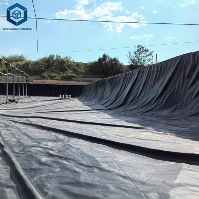
HDPE geomembrane (primary barrier)
Leak detection layer (optional)
Protective soil or concrete cover
Material Composition
Virgin HDPE resin with high molecular weight
2–3% carbon black for UV stability (if partially exposed)
Antioxidant stabilization package
Selecting which geomembrane for high groundwater level site projects requires evaluating both mechanical and hydraulic stability.
Manufacturing Process
Raw Material Verification: Resin density and melt index inspection.
Compounding: Uniform carbon black dispersion for consistent properties.
Extrusion: Blown film or flat die extrusion under controlled temperature.
Thickness Calibration: Automatic gauge control across sheet width.
Cooling & Stress Control: Gradual cooling to minimize internal stress.
Quality Testing: Tensile, puncture, OIT, and hydrostatic validation.
Strict quality control ensures performance under hydrostatic uplift conditions.
Industry Comparison
| Property | HDPE | LLDPE | PVC | EPDM |
|---|---|---|---|---|
| Uplift Resistance | High | Medium | Medium | Low |
| Chemical Resistance | Excellent | Very Good | Moderate | Good |
| Seam Strength | High (Fusion) | High | Adhesive-based | Adhesive-based |
| Long-Term Creep | Low | Moderate | Higher | Higher |
| Suitability for High Groundwater | Recommended | Conditional | Limited | Not Preferred |
HDPE is generally preferred when determining which geomembrane for high groundwater level site conditions due to stiffness and creep resistance.
Application Scenarios
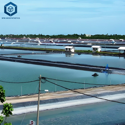
Landfills in coastal regions
Wastewater treatment lagoons
Underground storage basins
Mining tailings ponds
Industrial containment cells
Typical users include EPC contractors, environmental engineers, and infrastructure developers.
Core Pain Points & Engineering Solutions
1. Hydrostatic Uplift Pressure
Solution: Install subgrade drainage layer and increase liner thickness.
2. Liner Floating Risk
Solution: Use ballast layer or concrete cover to counter uplift forces.
3. Seam Separation Under Stress
Solution: Dual-track hot wedge welding with air channel testing.
4. Subgrade Instability
Solution: Improve soil compaction and provide geotextile reinforcement.
5. Long-Term Creep Deformation
Solution: Specify HDPE with verified creep resistance data.
Risk Warnings & Mitigation
Ignoring groundwater table fluctuation may cause uplift failure.
Underestimating thickness increases rupture risk.
Poor drainage design may create trapped pressure beneath liner.
Insufficient seam testing increases leakage exposure.
Improper anchor trench design may reduce edge stability.
Groundwater monitoring data should be integrated into final liner selection.
Procurement & Selection Guide
Determine maximum groundwater elevation and seasonal variation.
Calculate uplift pressure using hydrostatic head formula.
Select minimum 1.5–2.0 mm HDPE for moderate uplift conditions.
Design sub-liner drainage blanket to relieve pressure.
Confirm compliance with GRI GM13 performance standards.
Review seam strength and puncture resistance certification.
Request third-party test reports for mechanical validation.
Plan on-site welding QA/QC procedures.
This structured approach answers the question of which geomembrane for high groundwater level site development.
Engineering Case Study
Project: Coastal Wastewater Lagoon
Groundwater Level: 0.8 m below subgrade
Area: 12,000 m²
Liner Specification: 2.0 mm HDPE geomembrane
System: Drainage blanket + geotextile cushion + HDPE liner + soil ballast
Testing: Air channel seam testing + vacuum box inspection
Result: No uplift deformation after 5 years of operation.
FAQ
1. Why is groundwater uplift critical?
It can cause liner floating and structural failure.
2. Is HDPE always required?
Generally preferred for high uplift conditions.
3. What minimum thickness is recommended?
1.5 mm for moderate, 2.0 mm+ for high uplift sites.
4. Can drainage eliminate uplift?
It reduces but may not fully eliminate hydrostatic pressure.
5. Is ballast mandatory?
Required when uplift exceeds liner self-weight.
6. How are seams tested?
Air channel pressure and vacuum box methods.
7. Does groundwater chemistry matter?
Yes, chemical compatibility must be verified.
8. Is leak detection recommended?
For critical containment facilities, yes.
9. Can thinner liner be used with thicker cover soil?
Only if structural calculations confirm stability.
10. Should third-party inspection be included?
Recommended for regulated or large-scale projects.
Request Quotation or Technical Documentation
For project evaluation on which geomembrane for high groundwater level site conditions, submit groundwater data, soil reports, and design drawings. Our technical team can provide thickness calculation support, system design recommendations, and formal commercial quotation.
Author & Technical Authority
This article is prepared by a geosynthetics engineering consultant with over 15 years of experience in landfill, wastewater, and coastal containment systems. All specifications align with ASTM and GRI standards to support engineering-grade procurement decisions.