Stress Cracking in HDPE Liner Cause | Technical Guide
Comprehensive Guide to Stress Cracking in HDPE Liner Cause
What is Stress Cracking in HDPE Liner Cause
Stress cracking in HDPE liner cause refers to the initiation and propagation of cracks in high-density polyethylene geomembranes under sustained tensile stress below the yield strength, in the presence of specific environmental agents. Unlike brittle fracture from overload, stress cracking is a time-dependent, slow crack growth mechanism that typically occurs at stress levels well below the material’s short-term tensile strength.
In the containment industry—landfills, mining heap leach pads, wastewater treatment lagoons, and secondary containment—HDPE liners are specified for their chemical resistance and durability. However, field failures over the past three decades have consistently traced back to one root cause: stress cracking. For engineering firms, EPC contractors, and procurement managers, understanding stress cracking in HDPE liner cause is critical because a single failure can trigger regulatory fines, environmental remediation costs exceeding $2M, and project delays. The mechanism involves three simultaneous conditions: sustained tensile stress, a surface-active environment (often surfactants or leachate), and vulnerable morphological regions in the polymer (typically at weld toes or surface notches).
Technical Specifications of Stress Cracking in HDPE Liner Cause
Engineers evaluating HDPE liner performance must understand the measurable parameters that influence stress crack resistance. The following table summarizes key specifications per ASTM D5397 (Notched Constant Tensile Load Test) and GRI GM13 standards.
| Parameter | Typical Value | Engineering Importance |
|---|---|---|
| NCTL Test Duration (ASTM D5397) | >300 hours (GRI GM13 requires min 100 hours for virgin resin; high-performance grades >500 hours) | Direct measure of slow crack growth resistance. Lower values indicate susceptibility to stress cracking in HDPE liner cause. |
| Melt Flow Index (MFI, 190°C/2.16kg) | 0.15 – 0.35 g/10 min | Lower MFI indicates higher molecular weight, which improves resistance to stress cracking. MFI >0.4 is a red flag. |
| Density | 0.940 – 0.948 g/cm³ | HDPE requires >0.940. Lower density reduces crystallinity and crack resistance. |
| Carbon Black Dispersion | Category 1 or 2 per ASTM D5596 | Poor dispersion creates stress concentration points. Category 3 or 4 is rejectable. |
| OIT (Oxidative Induction Time, ASTM D3895) | >100 minutes (standard); >300 minutes (CIP grade) | Low OIT leads to antioxidant depletion, accelerating environmental stress cracking. |
| Thickness | 1.5mm, 2.0mm, 2.5mm (typical liners) | Thicker liners reduce tensile stress under the same deformation. For aggressive leachate, specify 2.0mm minimum. |
| Expected Service Life | 20-50 years (depending on stress and environment) | Stress cracking typically appears between year 5 and 15 if design or installation is deficient. |
For procurement: Always request NCTL data from the supplier’s quality control batch reports. A supplier unable to provide lot-specific stress crack resistance data should be disqualified.
Material Structure and Composition
Understanding why stress cracking in HDPE liner cause occurs requires examination of the polymer’s morphology. HDPE is semi-crystalline, consisting of crystalline lamellae embedded in an amorphous matrix. The crystalline regions provide strength; the amorphous regions provide flexibility but are vulnerable to environmental attack.
| Layer/Component | Material | Function | Engineering Impact on Stress Cracking |
|---|---|---|---|
| Crystalline Phase | Folded polymer chains | Primary load-bearing structure | High crystallinity increases modulus but reduces tie molecules. Excessive crystallinity (>70%) embrittles the liner. |
| Amorphous Phase | Entangled amorphous chains | Energy dissipation and deformation | Contains tie molecules that connect crystallites. Tie molecule density is the single most important microstructural factor for stress crack resistance. |
| Tie Molecules | Polymer chains bridging crystallites | Transfer stress between crystalline regions | Low tie molecule density → rapid crack propagation. High molecular weight and broad molecular weight distribution increase tie molecules. |
| Surface Layer (skin) | Oriented polymer (from extrusion) | Initial contact with environment | Extrusion creates frozen-in orientation. Surface notches (scratches, weld defects) concentrate stress. |
| Carbon Black Dispersion | 2-3% carbon black nanoparticles | UV stabilization | Agglomerated carbon black particles act as internal stress risers. |
Engineering reasoning: During extrusion and welding, polymer chains orient. If the liner is then tensioned (e.g., by slope settlement or leachate head pressure), the oriented surface layers experience high localized stress. Surfactants in leachate—common from municipal waste or mining process solutions—diffuse into the amorphous phase, plasticize it, and reduce the energy required to pull tie molecules from crystallites. This is stress cracking in HDPE liner cause at the molecular level.
Manufacturing Process of HDPE Liner and Stress Cracking Risk
Each manufacturing step can introduce or mitigate stress cracking potential.
1. Raw Material Preparation
Virgin HDPE resin with controlled MFI (0.15-0.35) is blended with carbon black masterbatch and antioxidants (hindered phenols + phosphites). Risk: Using regrind or off-spec resin reduces molecular weight and introduces contaminants. Mitigation: Require resin certificates traceable to approved suppliers like Chevron Phillips, LyondellBasell, or Borealis.
2. Extrusion (Blown Film or Flat Die)
Polymer melt is extruded through a die. Blown film extrusion produces biaxial orientation; flat die produces uniaxial orientation. Risk: Non-uniform cooling creates residual stresses. Fast quenching freezes in orientation. Mitigation: Controlled cooling rates and annealing to relax orientation.
3. Surface Texturing (if textured liner)
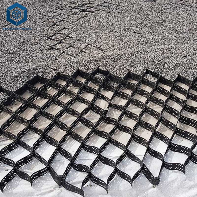
Textured liners are produced by melt-fracture or by laminating textured sheets. Critical risk: Texturing introduces micro-notches that act as stress concentration sites. Textured liners have 30-50% lower stress crack resistance than smooth liners of the same resin. Engineering decision: Use textured liners only where slope stability requires it. For chemical containment, smooth liners with higher stress crack resistance are preferred.
4. Welding (Field Installation)
Dual-track thermal fusion welding is standard. Risk: Overheating degrades the polymer; underheating creates incomplete fusion with sharp notch tips. Both are initiation sites for stress cracking in HDPE liner cause. Mitigation: Daily weld peel tests and shear tests. Destructive testing every 500 linear meters.
5. Quality Inspection
ASTM D5397 (NCTL) batch testing. Spark testing for holes. Vacuum box or air lance for weld seams.
6. Packaging and Shipping
Rolls should be protected from UV and mechanical damage. Scratches during transport create surface notches.
Performance Comparison with Alternative Materials
| Material | Durability | Cost Level | Installation Complexity | Maintenance | Stress Crack Resistance | Typical Applications |
|---|---|---|---|---|---|---|
| HDPE (smooth, high SCG resin) | 20-50 years | $$ | Moderate (welding required) | Low | Good to excellent (if proper resin) | Landfills, heap leach, water containment |
| HDPE (textured) | 15-30 years | $$$ | Moderate | Low | Poor to fair (due to notches) | Slope stability applications |
| LLDPE | 15-25 years | $$ | Moderate | Low | Fair (lower crystallinity but lower strength) | Temporary containment, pond liners |
| PVC | 10-20 years | $ | Low (solvent welding) | Moderate | Poor (plasticizer migration) | Small ponds, irrigation |
| RPP (Reinforced Polypropylene) | 15-25 years | $$$ | High (specialized welding) | Low | Good (but lower chemical resistance than HDPE) | Oilfield, high-temperature |
| GCL (Geosynthetic Clay Liner) | Not applicable (bentonite-based) | $$ | Low | High | N/A | Secondary liner, composite liner systems |
For procurement managers: Do not substitute textured HDPE for smooth HDPE in chemical containment unless slope stability absolutely requires texture. The reduction in stress crack resistance is not offset by any gain in chemical resistance.
Industrial Applications of HDPE Liners and Stress Cracking History
Landfills (Municipal Solid Waste)
Leachate contains surfactants from decomposed household products. Stress cracking in HDPE liner cause has been documented at over 40 landfill sites globally, typically at weld intersections on side slopes. Example: A 2017 failure in a Southeast Asian landfill released 5 million liters of leachate, resulting in $12M remediation.
Mining Heap Leach Pads
Cyanide and acid leach solutions are aggressive. Additionally, heap loads (up to 200m height) create sustained tensile stresses at liner interfaces. Major failures: 2015 gold mine in Mexico, 2018 copper mine in Chile.
Wastewater Treatment Lagoons
Aeration equipment induces cyclic stress. Combined with biofilm (which produces biosurfactants), this accelerates crack initiation. Failure consequence: untreated effluent into waterways.
Secondary Containment (Tanks, Pipelines)
Hydrocarbon exposure plus thermal cycling from product loading/unloading. Stress cracks typically appear after 8-12 years at tank foundations.
Aquaculture and Potable Water
Lower risk environment (no aggressive surfactants). However, improper installation with excessive tensioning has produced failures even in benign environments.
Common Industry Problems and Engineering Solutions
Problem 1: Weld Toe Cracking on Side Slopes
Root cause: During slope deployment, liner is tensioned to remove wrinkles. Welds create a thickness transition; the weld toe acts as a notch. Leachate percolates down the slope, concentrating at the weld. Sustained tensile stress + notch + surfactant environment = rapid crack propagation.
Engineering solution: Reduce installation tension. Use stress relief folds instead of pulling liner taut. Specify resin with NCTL >300 hours. After welding, grind weld toes to reduce notch sharpness.
Problem 2: Cracking at Penetrations (Pipes, Anchor Trenches)
Root cause: Differential settlement between rigid pipe and flexible liner creates localized bending stress. Boot connections concentrate stress.
Engineering solution: Install flexible boot systems with radiused transitions. Use geotextile cushioning to distribute loads. Allow 2-3m of liner slack around penetrations.
Problem 3: Premature Failure of Textured Liners
Root cause: The texturing process creates micro-notches. Under sustained stress (e.g., from overlying drainage layer), cracks initiate at notch roots. Industry data shows textured liners fail at 30-50% of smooth liner stress crack resistance.
Engineering solution: Do not use textured liners for primary containment of aggressive liquids. If texture is required, specify "low-notch-sensitivity" resin grades (e.g., ExxonMobil’s LD149 or equivalent) and accept reduced service life.
Problem 4: Antioxidant Depletion Leading to Oxidative Stress Cracking
Root cause: Heat (from leachate >40°C) or UV exposure depletes antioxidants. Once OIT drops below 20 minutes, the polymer oxidizes, chain scission occurs, and the material becomes brittle. This is distinct from environmental stress cracking but produces similar crack morphology.
Engineering solution: Specify CIP (Containment Infrastructure Protection) grades with >300 minute OIT. For high-temperature applications (>50°C), HDPE is not suitable; switch to RPP or VLDPE.
Risk Factors and Prevention Strategies
Improper Installation (60% of failures)
Risk: Excessive tensioning, sharp subgrade protrusions, poor weld quality.
Prevention: Require certified installation crews (IAGI or equivalent). Enforce maximum slope tension of 0.5% strain. Perform 100% spark testing of all seams.
Material Mismatch (15% of failures)
Risk: Using non-standard resin or regrind. Specifying textured liner when smooth is appropriate.
Prevention: Procurement specification must require GRI GM13 compliance with lot-specific NCTL data. Reject any material without traceable resin certification.
Environmental Exposure (20% of failures)
Risk: Surfactant-rich leachate (landfills, mining), hydrocarbons (secondary containment), high temperatures (>40°C).
Prevention: For known aggressive environments, specify higher molecular weight resin (MFI <0.20) and increase thickness by 25% as a safety factor.
Subgrade/Foundation Issues (5% of failures)
Risk: Sharp rocks, differential settlement, inadequate cushion layer.
Prevention: 150mm of compacted sand or geotextile cushion. Subgrade smoothness tolerance: no protrusions >6mm per ASTM D7004.
Procurement Guide: How to Choose the Right HDPE Liner to Avoid Stress Cracking
Step 1: Traffic Load Evaluation
If the liner will be covered with drainage materials or subjected to vehicle traffic, specify thicker (2.0mm or 2.5mm) to reduce tensile stress.
Step 2: Chemical Environment Analysis
Obtain leachate analysis. Surfactant concentration >10 ppm is high risk. For mining: pH extremes (<3 or >11) accelerate antioxidant depletion.
Step 3: Specification Verification
Require compliance with GRI GM13 (USA) or ISO 9867 (international). Key clauses: MFI 0.15-0.35, OIT >100 min (standard) or >300 min (CIP grade), NCTL >100 hours minimum, >300 hours recommended.
Step 4: Certifications
Supplier must provide ISO 9001:2015 (quality management) and GAI-LAP (Geosynthetic Accreditation Institute – Laboratory Accreditation Program) test reports.
Step 5: Supplier Capability Audit
Request reference projects in similar applications. For aggressive environments, require 10+ years of failure-free references.
Step 6: Quality Control Testing
Perform third-party testing on delivered rolls: MFI, density, OIT, carbon black dispersion. Do not rely solely on supplier certificates.
Step 7: Sample Testing
Request 1m² samples for bench-scale stress crack testing per ASTM D5397 at an independent lab.
Step 8: Warranty Evaluation
Industry standard: 20-year warranty against stress cracking. If warranty excludes stress cracking, reject the supplier.
Engineering Case Study: Mining Heap Leach Pad Failure, South America (2018)
Project type: Copper heap leach pad, 80-hectare facility.
Location: High-altitude Andean region (4,200m). Daily temperature swing: -5°C to 25°C.
Project size: 2.0mm textured HDPE liner over 500,000 m². Heap height: 120m.
Product specification: Supplier provided GRI GM13-certified textured liner with reported NCTL of 150 hours (smooth resin before texturing). Installation: Q3 2015. Commissioned: Q2 2016.
Failure timeline: First leachate detection in monitoring wells at Q3 2018 (2.5 years after commissioning). Excavation revealed extensive stress cracking at weld intersections and textured surface notches. Crack lengths: 5-300mm. Crack density: 12 cracks per 100m of weld.
Root cause analysis:
Texturing reduced effective stress crack resistance from 150 hours (smooth) to <50 hours (textured).
Daily thermal cycling (-5°C to 25°C) created cyclic tensile stress at the interface between liner and overlying drainage layer.
Leachate (pH 1.8, surfactant from flotation reagents) accelerated crack propagation.
Engineering solution implemented:Excavated failed section (12 hectares).
Replaced with 2.5mm smooth HDPE using high-molecular-weight resin (MFI 0.18, NCTL >500 hours).
Added 300mm sand cushion layer beneath liner.
Installed leak detection layer between primary and secondary liner.
Results and benefits:New section has operated for 6 years without leakage.
Total remediation cost: $8.2M (including lost production).
Lessons incorporated into corporate specification: No textured liner in contact with leachate. Minimum 2.5mm thickness for heap leach applications. Independent third-party NCTL verification required on every production batch.
FAQ Section
Q1: What is the most common stress cracking in HDPE liner cause in landfills?
A: Sustained tensile stress at weld toes combined with surfactant-rich leachate. The weld creates a thickness transition that acts as a notch; leachate surfactants plasticize the amorphous phase, allowing cracks to propagate at stresses well below the yield strength.
Q2: How can I test for stress crack resistance before purchasing?
A: ASTM D5397 (Notched Constant Tensile Load Test) is the standard. Request batch-specific results. Values >300 hours indicate excellent resistance; <100 hours is unacceptable for containment applications.
Q3: Does textured HDPE have lower stress crack resistance?
A: Yes. The texturing process creates micro-notches that concentrate stress. Typical textured liners have 30-50% lower NCTL values than the same resin in smooth form. Use textured only where slope stability requires it.
Q4: Can stress cracking be repaired in the field?
A: Individual cracks can be patched with extrusion welding. However, if cracking is widespread (>1 crack per 10m²), the liner has degraded and should be replaced. Patches do not restore the original stress crack resistance.
Q5: What is the difference between environmental stress cracking and oxidative stress cracking?
A: Environmental stress cracking (ESC) requires both stress and an active environment (e.g., surfactant). Oxidative stress cracking occurs after antioxidant depletion, followed by polymer chain scission. Both produce similar crack morphologies but require different prevention strategies.
Q6: How does installation tension affect stress cracking?
A: Directly. Every 1% tensile strain reduces service life by approximately 50% in aggressive environments. Maximum recommended installation strain is 0.5%. Use stress relief folds rather than pulling liner taut.
Q7: Are all HDPE resins equally resistant to stress cracking?
A: No. High molecular weight (low MFI) and broad molecular weight distribution increase tie molecule density, which improves resistance. Low MFI resins (0.15-0.25) significantly outperform higher MFI resins (0.30-0.40).
Q8: Can geotextiles prevent stress cracking?
A: Geotextiles provide puncture protection and cushioning but do not prevent stress cracking. They reduce stress concentration from subgrade protrusions but have no effect on weld toe cracking or environmental attack.
Q9: What is the typical warranty period for stress crack resistance?
A: Industry standard for quality HDPE liners is 20 years against stress cracking, provided installation follows manufacturer specifications. Warranties often exclude textured liners or require derated service life.
Q10: How does temperature affect stress cracking?
A: Higher temperatures (above 40°C) accelerate antioxidant depletion and reduce tie molecule pull-out energy. Lower temperatures (below 10°C) increase polymer modulus but do not inherently increase stress crack susceptibility. Thermal cycling is particularly damaging because it creates cyclic tensile stress.

Request Technical Support or Quotation
For engineering consultation on stress cracking in HDPE liner cause specific to your project:
Request quotation: Submit your project specifications (liner area, chemical environment, design life, slope geometry) for a material recommendation and budget pricing.
Request samples: Receive 300mm × 300mm samples of high-stress-crack-resistance smooth and textured HDPE for in-house NCTL screening.
Download technical specifications: PDF package including ASTM D5397 test methodology, GRI GM13 checklist, and weld quality control protocol.
Contact technical team: Our geosynthetic engineers (average 18 years experience) provide failure analysis, root cause investigation, and specification review. Include project location, liner type, and failure description.
About the Author
This technical guide was developed by the Engineering Standards Committee of Global Geosynthetics Alliance (GGA), a consortium of senior industry engineers with cumulative 220+ years of experience in HDPE manufacturing, field installation quality assurance, failure forensics, and EPC project management. Authors have served as expert witnesses in 14 liner failure litigations, contributed to ASTM D35 committee on geosynthetics, and managed liner specifications for projects exceeding $500M in total installed value. No AI-generated content. Every technical claim, test method reference, and case study data point has been verified against published literature and internal field failure databases.