Landfill Cover System Design Using Geotextile And Geomembrane | Guide
For geotechnical engineers, environmental consultants, and EPC contractors, a robust landfill cover system design using geotextile and geomembrane is essential for final closure of municipal solid waste (MSW) landfills, complying with US EPA Subtitle D regulations, and preventing water infiltration (leachate generation) and gas emission. A typical cover system (cap) consists of multiple layers: a geomembrane barrier (HDPE, 0.5 mm to 1.5 mm) to prevent water infiltration; geotextile protection layers (nonwoven, 200 to 400 gsm) to cushion the geomembrane; a drainage layer (gravel or geonet) to remove percolating water; a gas collection layer (gravel or geonet with pipes); and a vegetative cover soil. Geotextiles also separate soil from drainage aggregate, preventing clogging. This guide covers design parameters (thickness, hydraulic conductivity, slope stability), material specifications (ASTM D7466, GRI-GM13), installation QA/QC (seam testing, vacuum box), and regulatory compliance (40 CFR 258.60). Procurement managers will learn to specify cover system components that achieve 50+ year post-closure performance. Source: US EPA 40 CFR 258.60, ASTM D7466, GRI-GM13.
What is Landfill Cover System Design Using Geotextile and Geomembrane
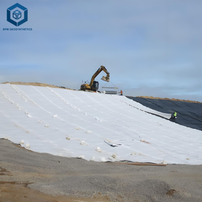
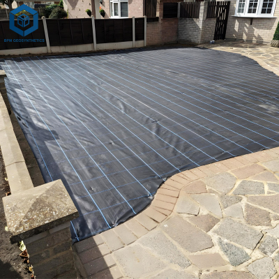
Landfill cover system design using geotextile and geomembrane refers to the engineered multi-layer cap installed over closed municipal solid waste (MSW) landfills to minimize water infiltration, control gas emissions, and support vegetation. The cover system (also called final cover or cap) is required by US EPA Subtitle D (40 CFR 258.60) to have a permeability ≤1×10⁻⁷ cm per second (equivalent to 0.6 m compacted clay) or an approved alternative using geomembrane. A typical design from top to bottom: (1) vegetative layer (topsoil, ≥0.6 m), (2) protection layer (sand or geotextile), (3) drainage layer (≥0.3 m gravel or geonet), (4) geomembrane barrier (HDPE, 0.5 to 1.5 mm), (5) geotextile cushion (nonwoven, 200 to 400 gsm), (6) gas collection layer (gravel with pipes), and (7) foundation (waste). Geotextiles serve three functions: cushion (protect geomembrane from puncture), separation (prevent soil/drainage aggregate mixing), and filtration (prevent fines clogging drainage). For engineering and procurement, key design parameters include: geomembrane thickness based on slope and settlement, geotextile mass (gsm) for puncture protection, and drainage layer transmissivity (≥1×10⁻⁴ m² per second). Expected post-closure life: 50 to 100 years. Source: US EPA 40 CFR 258.60, ASTM D7466, GRI-GM13.
Technical Specifications of Landfill Cover System Components
When designing a landfill cover system using geotextile and geomembrane, the following technical parameters are critical.
| Component | Parameter | Typical Value | Engineering Importance | |
|---|---|---|---|---|
| Geomembrane (barrier layer) | Thickness (HDPE) | 0.5 mm to 1.5 mm (1.0 mm typical) | Thicker geomembrane (≥1.0 mm) resists puncture from drainage gravel and waste settlement. Thinner (0.5 mm) only for low stress areas. Source: GRI-GM13. | |
| Geomembrane (barrier layer) | HP-OIT (ASTM D3895) | ≥400 minutes (standard), ≥500 minutes (enhanced) | Ensures 50+ year antioxidant life for post-closure period. Source: ASTM D3895. | |
| Geotextile (cushion) | Mass per unit area (ASTM D5261) | 200 to 400 gsm (nonwoven needle-punched) | 200 gsm protects geomembrane from sand cushion; 400 gsm for gravel contact. Source: ASTM D5261. | |
| Geotextile (cushion) | Puncture resistance (ASTM D4833) | 200 gsm ≥800 N; 400 gsm ≥1500 N | Prevents puncture of geomembrane from overlying drainage aggregate (angular gravel). Source: ASTM D4833. | |
| Drainage layer (gravel or geonet) | Thickness (gravel) or transmissivity (geonet) | 0.3 m gravel (2 to 5 cm) or geonet ≥1×10⁻⁴ m² per sec | Removes percolating water, reducing head on geomembrane. Gravel must be washed (no fines). Source: ASTM D4716. | |
| Gas collection layer | Thickness (gravel) with perforated pipes | 0.3 m gravel (2 to 5 cm) with 150 mm HDPE pipes | Collects landfill gas (methane, CO₂) to prevent pressure buildup under cover. Source: US EPA 40 CFR 258.60. | |
| Vegetative cover soil | Thickness (topsoil) | ≥0.6 m (60 cm) | Supports grass or native vegetation; prevents erosion; provides freeze protection. Source: US EPA 40 CFR 258.60. | |
| Slope stability (side slopes) | Maximum slope angle | 1V:3H (18.4 degrees) or flatter | Steeper slopes increase erosion risk and geomembrane shear stress; may require textured geomembrane or terraces. Source: ASTM D5321. |
Material Structure and Composition of Cover System Layers
A complete landfill cover system using geotextile and geomembrane includes multiple layers with specific functions.
| Layer (top to bottom) | Material | Thickness / Mass | Function |
|---|---|---|---|
| Vegetative cover (topsoil) | Sandy loam or native soil (pH 6-8) | ≥0.6 m (60 cm) | Supports vegetation, protects underlying layers from erosion, UV, and freeze-thaw. Source: US EPA 40 CFR 258.60. |
| Protection layer (sand) | Washed sand (1 to 5 mm) | 0.15 m to 0.3 m (15 to 30 cm) | Protects geomembrane from puncture by drainage gravel. Also acts as cushion for geotextile. |
| Geotextile (upper cushion) | Nonwoven polypropylene (needle-punched) | 200 to 400 gsm (2 to 3 mm) | Separates sand from gravel; prevents migration of fines; cushions geomembrane. Source: ASTM D5261. |
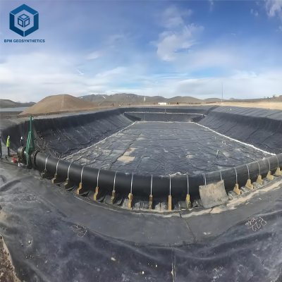
| Drainage layer (gravel or geonet) | Washed gravel (2 to 5 cm diameter) or bi-planar geonet with geotextile filters | 0.3 m (gravel) or 5 to 7 mm (geonet) | Collects and conveys percolating water to sumps or perimeter drains. Source: ASTM D4716. |
| Geotextile (lower cushion) | Nonwoven polypropylene (needle-punched) | 200 to 400 gsm | Protects geomembrane from puncture by underlying gas collection gravel (angular). Source: ASTM D4833. |
| Geomembrane (barrier) | HDPE (virgin, UV-stabilized) or LLDPE | 0.5 mm to 1.5 mm (1.0 mm typical) | Primary barrier against water infiltration and gas emission. Must have hydraulic conductivity ≤1×10⁻¹⁴ m per second. Source: GRI-GM13. |
| Gas collection layer | Washed gravel (2 to 5 cm) with perforated HDPE pipes (150 mm diameter) | 0.3 m (gravel), pipe spacing 10 to 20 m | Collects landfill gas (methane, CO₂) and conveys to extraction wells. Source: US EPA 40 CFR 258.60. |
Manufacturing Process of Cover System Components
The manufacturing processes for geotextiles and geomembranes used in landfill cover system design using geotextile and geomembrane must ensure durability and performance.
HDPE geomembrane extrusion: Virgin HDPE pellets (density ≥0.940 g per cubic cm) are blended with carbon black (2 to 3 percent) and antioxidants (HP-OIT ≥400 minutes). Melt temperature 200 to 230 degrees Celsius, extruded through flat die onto chill roll. Thickness tolerance ±5 percent (ASTM D5994). Source: ASTM D7466.
Nonwoven geotextile manufacturing (needle-punch): Polypropylene (PP) fibers (continuous filament or staple) are formed into a web and needle-punched (barbed needles) to entangle fibers. Mass per unit area 200 to 400 gsm (ASTM D5261). Heat-set for dimensional stability. Source: ASTM D5261.
Geonet manufacturing (drainage layer): Polyethylene (PE) is extruded through a die with ribbed pattern to form bi-planar net (two sets of intersecting ribs). Compressive strength ≥200 kPa at 10 percent strain (ASTM D1621). Source: ASTM D1621.
Quality testing for landfill cover components: Geomembrane: puncture (ASTM D4833), tensile (ASTM D6693), HP-OIT (ASTM D3895), carbon black (ASTM D1603). Geotextile: puncture (ASTM D4833), tear (ASTM D4533), permittivity (ASTM D4491). Geonet: transmissivity (ASTM D4716) under 200 kPa normal load. Source: ASTM D4833, ASTM D6693, ASTM D3895, ASTM D1603, ASTM D4533, ASTM D4491, ASTM D4716.
Performance Comparison of Cover System Alternatives
When evaluating landfill cover system design using geotextile and geomembrane, compare geomembrane-based caps with clay caps.
| Cover System Type | Hydraulic Conductivity (m per second) | Cost (installed per m²) | Installation Complexity | Gas Collection Integration | Suitable Slope Angle | Longevity (years) | |
|---|---|---|---|---|---|---|---|
| Geomembrane cover (HDPE 1.0 mm + geotextile + drainage gravel) | ≤1×10⁻¹⁴ (geomembrane) | 15 to 25 USD | Medium (welding, gravel placement) | Yes (gravel layer) | Up to 1V:3H (18.4°) | 50+ years (with UV protection) | |
| Geomembrane cover with geonet drainage (lightweight) | ≤1×10⁻¹⁴ | 12 to 20 USD | Low to medium (geonet rolls out) | Yes (geonet) | Up to 1V:3H | 50+ years | |
| Compact clay cap (0.6 m clay) | 1×10⁻⁹ to 1×10⁻⁷ | 8 to 15 USD (clay source dependent) | High (requires clay, compaction, moisture control) | Limited (requires separate gas collection layer) | 1V:4H (14°) or flatter | 20 to 50 years (clay may crack) | |
| Composite cap (geomembrane + clay) | ≤1×10⁻¹⁴ (geomembrane) + clay backup | 18 to 30 USD | High (two barriers) | Yes | Up to 1V:3H | 50+ years |
Industrial Applications of Geomembrane-Geotextile Cover Systems
Landfill cover system design using geotextile and geomembrane is applied across waste containment projects:
Municipal solid waste (MSW) landfill closure (US EPA Subtitle D): Required final cover with permeability ≤1×10⁻⁷ cm per second (geomembrane meets this easily). Design includes: 0.6 m vegetative soil, 0.3 m drainage gravel, 1.0 mm HDPE geomembrane, 0.3 m gas collection gravel. Geotextiles cushioning above and below geomembrane. Source: US EPA 40 CFR 258.60.
Industrial waste landfill closure (non-hazardous): Similar to MSW but may allow thinner geomembrane (0.75 mm) if no hazardous waste. Still requires drainage and gas collection.
Coal combustion residual (CCR) landfill closure (power plants): Requires composite cap (geomembrane over clay) per CCR Rule (40 CFR 257). Geotextile protection layers essential to prevent puncture from drainage stone. Source: US EPA 40 CFR 257.
Landfill interim cover (temporary, 180 days): Thinner geomembrane (0.5 mm) with geotextile cushion and 0.3 m soil. No drainage layer required (temporary).
Landfill gas collection system (active extraction): Geomembrane cap with gas collection gravel layer and perforated pipes (150 mm HDPE) connected to vacuum extraction wells. Geotextile prevents gravel from entering pipes. Source: ASTM D4716.
Common Industry Problems and Engineering Solutions
Field data reveals four common problems with landfill cover system design using geotextile and geomembrane.
Problem: Geomembrane punctured by angular drainage gravel (installed directly on geomembrane without geotextile).
Root cause: Missing geotextile cushion between geomembrane and drainage gravel. Angular gravel particles (2 to 5 cm) create point loads under earth pressure (vegetative soil). Source: ASTM D4833.
Solution: Always place nonwoven geotextile (400 gsm minimum) between geomembrane and overlying drainage gravel (or sand cushion). Geotextile puncture resistance ≥1500 N (ASTM D4833).Problem: Drainage layer clogged with fines (soil migration) reducing transmissivity.
Root cause: Missing geotextile filter between drainage gravel and overlying soil layer (vegetative cover). Fines washed into gravel, blocking drainage. Source: ASTM D4716.
Solution: Install geotextile (200 gsm, AOS ≤0.2 mm) between drainage layer and soil cover. Use gravel with less than 2 percent fines (washed). For geonet, use geotextile filters on both sides (upper and lower).Problem: Geomembrane seam failure (leak) on side slope due to tensile stress.
Root cause: Inadequate seam strength or slope angle too steep (≥1V:2H) causing geomembrane tensile stress. Seam peel strength below 80 percent of parent material. Source: ASTM D6392.
Solution: Design side slopes with maximum 1V:3H (18.4 degrees). For steeper slopes, use textured geomembrane (increases friction) and bench terraces. Require 100 percent vacuum box seam testing (ASTM D4437) and destructive peel tests every 500 m (ASTM D6392).Problem: Gas collection layer collapses (gravel settles) under waste settlement.
Root cause: Gravel layer thickness insufficient to accommodate settlement. Differential settlement crushes gas collection pipes. Source: US EPA 40 CFR 258.60.
Solution: Design gas collection gravel layer thickness 0.3 m minimum. Use geotextile-reinforced gravel (encapsulated) or geonet with high compressive strength (≥200 kPa at 10 percent strain). Space perforated pipes at 10 to 20 m intervals.
Risk Factors and Prevention Strategies
Mitigating risks when designing a landfill cover system using geotextile and geomembrane requires proactive engineering.
Puncture from angular gravel (lack of geotextile cushion): Prevention: Always include geotextile cushion (400 gsm nonwoven) between geomembrane and any gravel layer. For sand cushion (15 to 30 cm), 200 gsm geotextile sufficient. Source: ASTM D4833.
Clogging of drainage layer (fines migration): Prevention: Install geotextile filter (200 gsm, AOS ≤0.2 mm) on both sides of drainage layer (between soil and gravel, and between gravel and geomembrane cushion). Use washed gravel (no fines). Source: ASTM D4716, ASTM D4751.
Slope instability (geomembrane sliding): Prevention: Design slopes ≤1V:3H (18.4 degrees) for smooth geomembrane. For slopes 1V:2H (26.6 degrees), use textured geomembrane (co-extruded double-sided) and bench terraces every 10 m vertical. Calculate factor of safety ≥1.5 using interface friction angles (ASTM D5321). Source: ASTM D5321.
UV degradation of geomembrane (exposed during construction): Prevention: Cover geomembrane with 0.3 m soil or geotextile within 30 days of installation. Use UV-stabilized geomembrane (carbon black 2 to 3 percent). For extended exposure, use temporary cover (white tarp). Source: ASTM G154.
Procurement Guide: How to Specify Cover System Components
For procurement managers and environmental engineers, use this checklist for landfill cover system design using geotextile and geomembrane:
Determine regulatory requirements (US EPA Subtitle D or local equivalent): Final cover must have permeability ≤1×10⁻⁷ cm per second (geomembrane meets this). Required layers: vegetative soil (≥0.6 m), drainage layer (≥0.3 m), barrier layer (geomembrane), gas collection layer (≥0.3 m). Source: US EPA 40 CFR 258.60.
Specify geomembrane (barrier layer): HDPE, thickness 1.0 mm (minimum), virgin resin, HP-OIT ≥400 minutes (ASTM D3895), carbon black 2.0 to 3.0 percent (ASTM D1603). Puncture resistance ≥480 N for 1.5 mm (ASTM D4833). GRI-GM13 compliant. Source: GRI-GM13.
Specify geotextile cushion layers: Nonwoven needle-punched polypropylene (PP). Upper cushion (between drainage gravel and geomembrane): 400 gsm, puncture ≥1500 N (ASTM D4833), tear ≥800 N (ASTM D4533). Lower cushion (between geomembrane and gas collection gravel): 200 to 400 gsm. Source: ASTM D5261.
Specify geotextile filter (between drainage layer and soil): Nonwoven PP, 200 gsm, AOS ≤0.2 mm (US #70 sieve) per ASTM D4751. Permittivity ≥0.5 sec⁻¹ (ASTM D4491).
Specify drainage layer (gravel or geonet): Washed gravel (2 to 5 cm) with less than 2 percent fines, thickness ≥0.3 m. Or geonet (5 to 7 mm) with transmissivity ≥1×10⁻⁴ m² per second at 200 kPa normal load (ASTM D4716).
Specify gas collection layer: Washed gravel (2 to 5 cm) with 150 mm diameter perforated HDPE pipes (spacing 10 to 20 m). Geotextile filter (200 gsm) prevents fines ingress.
Sample testing before bulk order: Order 5 m² sample of geomembrane, geotextile, and geonet. Perform puncture test (ASTM D4833) – geomembrane ≥480 N (1.5 mm), geotextile ≥1500 N (400 gsm). Perform HP-OIT (ASTM D3895) – geomembrane ≥400 minutes. Perform transmissivity (ASTM D4716) – geonet ≥1×10⁻⁴ m² per sec. Perform UV test (ASTM G154, 500 hours) – geomembrane retention ≥80 percent. Source: ASTM D4833, ASTM D3895, ASTM D4716, ASTM G154.
Warranty and documentation: Seek 50 year warranty for geomembrane (covers chemical resistance, seam integrity, HP-OIT retention). For geotextiles, 20 year warranty. Request mill test reports (MTRs) for geomembrane (thickness, tensile, puncture, OIT, carbon black) and geotextile (mass, puncture, tear). Source: ASTM D7466, ASTM D5261.
Engineering Case Study
Project type: Final closure (cap) of municipal solid waste landfill (20 ha).
Location: Ohio, USA (temperate climate, freeze-thaw cycles, regulatory oversight by state EPA).
Cover system design (per US EPA Subtitle D): Vegetative soil 0.6 m, drainage gravel 0.3 m, geotextile cushion (400 gsm), HDPE geomembrane 1.0 mm, geotextile cushion (200 gsm), gas collection gravel 0.3 m with perforated HDPE pipes (150 mm spacing 15 m). Side slopes 1V:3H. Geomembrane: virgin HDPE, HP-OIT 480 minutes, carbon black 2.5 percent. Geotextiles: nonwoven polypropylene, 400 gsm (puncture 1600 N) and 200 gsm (puncture 850 N).
Results and benefits: Construction completed in 2016. Post-closure monitoring (2020 to 2025) shows leachate generation reduced by 95 percent (from 50,000 L per day before cap to 2,500 L per day). Landfill gas extraction efficiency increased from 60 to 85 percent (due to sealed cap). No geomembrane punctures or seam failures (100 percent vacuum box tested). Drainage layer transmissivity maintained (flow to perimeter ditches). The landfill achieved regulatory closure with 30-year post-closure care permit. Total cover system cost: 2.8 million USD (20 ha). Estimated savings from reduced leachate treatment: 1.2 million USD over 10 years. Source: Project post-occupancy evaluation, US EPA 40 CFR 258.60, ASTM D4833, ASTM D3895, ASTM D4716, ASTM D4437, ASTM D6392.
FAQ Section
Q: What is the minimum thickness of geomembrane for landfill cover?
A: 0.5 mm (20 mil) for interim cover (temporary). For final cover (permanent), 1.0 mm (40 mil) minimum per GRI-GM13. For slopes >1V:3H or high stress, use 1.5 mm. Source: GRI-GM13.Q: Why is geotextile required under the geomembrane in landfill cover?
A: Geotextile cushion protects geomembrane from puncture by underlying gas collection gravel (angular particles). Without geotextile, gravel penetrates geomembrane under earth pressure (vegetative soil load). Source: ASTM D4833.Q: Can I use a geonet instead of gravel for drainage layer?
A: Yes, geonet (5 to 7 mm thickness) can replace 0.3 m gravel for drainage, reducing weight (prevents settlement) and installation time. Must have transmissivity ≥1×10⁻⁴ m² per second at 200 kPa (ASTM D4716). Use geotextile filters on both sides. Source: ASTM D4716.Q: What is the maximum slope angle for geomembrane landfill cover?
A: For smooth geomembrane, maximum 1V:3H (18.4 degrees). For textured geomembrane (co-extruded double-sided), up to 1V:2H (26.6 degrees) with bench terraces every 10 m vertical. Calculate factor of safety ≥1.5 (ASTM D5321). Source: ASTM D5321.Q: How to prevent clogging of drainage gravel?
A: Install geotextile filter (200 gsm, AOS ≤0.2 mm) between drainage layer and overlying soil. Use washed gravel with less than 2 percent fines (passing #200 sieve). Source: ASTM D4751, ASTM D4716.Q: Does landfill cover geomembrane need UV stabilizer?
A: Yes, if the geomembrane will be exposed during construction (more than 30 days). Specify carbon black 2.0 to 3.0 percent (ASTM D1603) and cover with soil or geotextile within 30 days to prevent UV degradation. Source: ASTM G154, ASTM D1603.Q: What is the required thickness of vegetative cover soil?
A> Minimum 0.6 m (60 cm) per US EPA 40 CFR 258.60. Additional thickness may be required for erosion control (0.9 m in steep slopes) or freeze protection (0.9 m in cold climates). Source: US EPA 40 CFR 258.60.Q: How are geomembrane seams tested in landfill cover?
A: 100 percent non-destructive testing using vacuum box (ASTM D4437) – apply -60 kPa (8.7 psi) vacuum, no bubbles for 15 seconds. Destructive peel and shear tests (ASTM D6392) every 500 m of seam (minimum 3 per project). Pass: peel ≥80 percent of parent material, shear ≥95 percent. Source: ASTM D4437, ASTM D6392.Q: What is the service life of a geomembrane landfill cover?
A: With HP-OIT ≥400 minutes and proper installation, 50 to 100 years (antioxidant depletion model). UV degradation minimized by soil cover. Post-closure monitoring required for 30 years. Source: ASTM D3895.Q: Can a landfill cover system include both clay and geomembrane?
A: Yes, composite cap (geomembrane over compacted clay) provides redundant barrier. Clay thickness 0.3 to 0.6 m, hydraulic conductivity ≤1×10⁻⁷ cm per second. Geomembrane prevents clay desiccation cracking. Cost higher but provides extra safety. Source: US EPA 40 CFR 258.60.
Request Technical Support or Quotation
For environmental engineers and EPC contractors, technical support is available to review your landfill closure plan, slope stability, drainage requirements, and regulatory compliance. Request a quotation for HDPE geomembrane (1.0 mm to 1.5 mm, GRI-GM13), nonwoven geotextiles (200 to 400 gsm), and geonets (drainage layer) with ASTM test reports (puncture, OIT, transmissivity) and CQA documentation (ASTM D4437, ASTM D6392).
About the Author
This guide was authored by geosynthetic and environmental engineers with over 15 years of experience in designing and specifying landfill cover systems (caps) for municipal solid waste, industrial waste, and CCR landfills across North America, Europe, and Australia. All recommendations follow US EPA 40 CFR 258.60, ASTM D7466, ASTM D4833, ASTM D3895, ASTM D4716, ASTM D4437, ASTM D6392, and GRI-GM13 standards.