How to choose geomembrane thickness for tailings pond
Product Definition
How to choose geomembrane thickness for tailings pond refers to the engineering process of determining the appropriate HDPE liner thickness required to ensure seepage control, chemical resistance, and long-term structural stability in mining tailings storage facilities (TSF). Thickness selection directly impacts containment safety, environmental compliance, and lifecycle cost.
Technical Parameters & Specifications
Thickness selection must be aligned with international geomembrane standards typically used in mining containment applications.
| Property | 1.0mm | 1.5mm | 2.0mm | Test Standard |
|---|---|---|---|---|
| Density | ≥ 0.94 g/cm³ | ASTM D1505 | ||
| Tensile Strength (Yield) | ≥ 15 kN/m | ≥ 22 kN/m | ≥ 29 kN/m | ASTM D6693 |
| Puncture Resistance | ≥ 300 N | ≥ 480 N | ≥ 640 N | ASTM D4833 |
| Environmental Stress Crack Resistance (ESCR) | ≥ 500 hrs | ASTM D5397 | ||
| Carbon Black Content | 2.0–3.0% | ASTM D4218 | ||
In most engineered tailings pond projects, 1.5mm–2.0mm HDPE geomembranes are commonly specified due to high mechanical and chemical demands.
Structure & Material Composition
Understanding material composition is fundamental when evaluating how to choose geomembrane thickness for tailings pond containment systems.
Base Polymer: Virgin high-density polyethylene (HDPE)
Carbon Black: UV stabilization and oxidation resistance
Antioxidant Package: Long-term thermal aging control
Stabilizers: Chemical and environmental protection
Surface Type: Smooth or textured (slope applications)
Thicker geomembranes provide higher resistance to differential settlement and tailings load pressure.
Manufacturing Process
1. Resin Blending
Precise mixing of HDPE resin with additives under controlled conditions.
2. Extrusion Process
Flat-die or blown-film extrusion at controlled melt temperatures (200–230°C) ensures sheet uniformity.
3. Thickness Control
Online automatic gauging systems maintain thickness tolerance within ±5%.
4. Surface Texturing (Optional)
Nitrogen injection or embossing creates textured surfaces for slope stability.
5. Quality Testing
Mechanical, chemical, and stress crack resistance testing prior to dispatch.
Industry Comparison
| Material | Thickness Range | Chemical Resistance | Durability | Tailings Suitability |
|---|---|---|---|---|
| HDPE | 1.0–3.0mm | Excellent | High | Highly Suitable |
| LLDPE | 0.75–2.0mm | Good | Moderate | Moderate |
| PVC | 0.8–2.0mm | Moderate | Lower | Limited |
| Clay Liner | 300–600mm | Variable | Settlement Sensitive | Requires Composite |
Application Scenarios
The decision process for how to choose geomembrane thickness for tailings pond varies by stakeholder:
EPC Contractors: Prefer ≥1.5mm for regulatory compliance.
Mining Developers: Often specify 2.0mm in high-risk containment zones.
Consulting Engineers: Determine thickness through slope stability and puncture analysis.
Distributors: Supply 1.5mm as standard mining grade inventory.
Core Pain Points & Engineering Solutions
1. Differential Settlement
Solution: Increase thickness to 1.5–2.0mm and integrate cushioning geotextile.
2. Chemical Attack from Acidic Tailings
Solution: Use virgin HDPE with certified chemical resistance testing.
3. Puncture from Subgrade Rocks
Solution: Conduct subgrade compaction and install protective geotextile layer.
4. Long-Term Stress Cracking
Solution: Specify high ESCR values and avoid recycled content.
Risk Warnings & Mitigation
Underestimating load pressure may cause liner rupture.
Improper welding reduces containment integrity.
Inadequate slope design increases sliding risk.
Ignoring UV exposure shortens service life in exposed zones.
Procurement Selection Guide
Conduct geotechnical investigation of subgrade soil.
Analyze tailings chemical composition and pH level.
Calculate hydrostatic and tailings load pressure.
Determine design service life (often ≥20 years).
Specify ASTM-compliant mechanical properties.
Confirm welding method and quality assurance plan.
Request third-party laboratory testing reports.
Evaluate total lifecycle cost rather than initial price.
Engineering Case Study
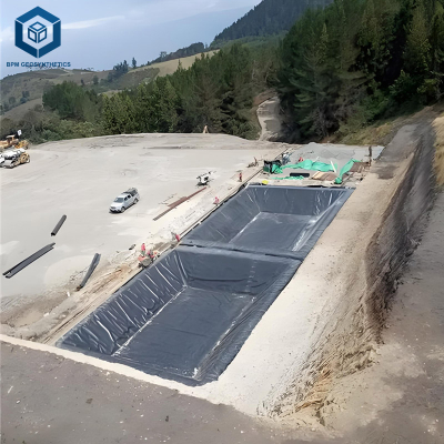
A copper mining project in South America required evaluation of how to choose geomembrane thickness for tailings pond expansion covering 25 hectares. The subgrade consisted of compacted silty clay with variable settlement risk.
Engineering analysis recommended 2.0mm textured HDPE geomembrane over 500g/m² nonwoven geotextile. Installation included anchor trenches (800mm depth), double-track welding, and full air-channel testing. After five years of operation, monitoring reports confirmed stable containment without leakage incidents.
FAQ
1. What is the typical thickness for tailings ponds?
1.5mm to 2.0mm HDPE is common in mining applications.
2. Is 1.0mm suitable?
Generally not recommended for primary containment.
3. Why is 2.0mm preferred?
Higher puncture resistance and longer service life.
4. Should textured geomembrane be used?
Yes, on slopes requiring higher friction.
5. What standards apply?
ASTM mechanical and stress crack resistance standards.
6. Is chemical compatibility critical?
Yes, especially for acidic or alkaline tailings.
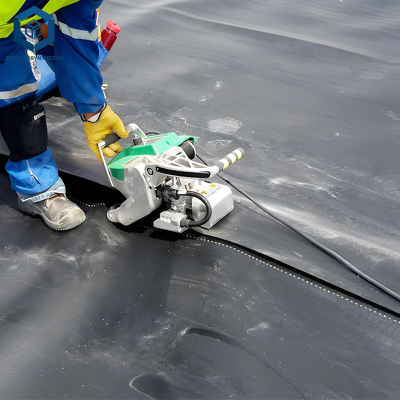
7. How is seam integrity verified?
Air pressure and vacuum box testing.
8. Can recycled material be used?
Not for high-risk containment systems.
9. What about exposed applications?
UV stabilization and protective cover are recommended.
10. Does thickness affect welding?
Yes, thicker sheets require adjusted welding parameters.
Request Technical Documentation
For detailed engineering calculations, thickness selection support, or formal quotation related to how to choose geomembrane thickness for tailings pond, please submit project drawings, geotechnical data, and chemical analysis reports. Technical data sheets, welding specifications, and material samples are available upon request.
Author & Technical Authority
This article is prepared by a geomembrane engineering specialist with over a decade of experience in mining containment systems, tailings storage facility design support, and international EPC collaboration. All technical guidance aligns with established ASTM testing standards and field installation best practices.