Textured vs Smooth HDPE Geomembrane for Slope Stability
Textured vs smooth HDPE geomembrane for slope stability refers to the technical comparison between standard smooth high-density polyethylene liners and textured-surface variants designed to enhance interface friction and prevent sliding on engineered slopes.
Technical Parameters and Specifications
When evaluating textured vs smooth HDPE geomembrane for slope stability, procurement teams must review measurable engineering properties rather than surface appearance alone.
Material: High-Density Polyethylene (HDPE), ≥97.5% polymer
Thickness range: 0.75 mm – 3.0 mm (30–120 mil)
Density: ≥0.940 g/cm³
Tensile strength (yield): ≥15 kN/m (1.5 mm typical)
Elongation at break: ≥700%
Carbon black content: 2–3%
Oxidative induction time (OIT): ≥100 min (Std OIT)
Surface friction angle (smooth): 11°–18° (soil interface dependent)
Surface friction angle (textured): 18°–30° (soil interface dependent)
Roll width: 5–8 m typical
For slope stability design, interface shear strength and friction angle are the decisive parameters.
Structure and Material Composition
Smooth HDPE Geomembrane Structure
Homogeneous HDPE resin
Carbon black UV stabilizer
Antioxidant package
Flat extrusion surface
Textured HDPE Geomembrane Structure
Same HDPE base polymer
Co-extruded or nitrogen-blown textured surface
Single-side or double-side roughness options
Enhanced asperity height (0.25–0.6 mm typical)
In textured vs smooth HDPE geomembrane for slope stability evaluation, the base resin remains identical; the surface morphology drives performance difference.
Manufacturing Process
Raw Material Feeding: Virgin HDPE resin mixed with carbon black and stabilizers.
Extrusion: Flat die extrusion at 200–240°C.
Texturing (if required): Nitrogen injection or patterned rollers to create asperities.
Thickness Calibration: Automated gauge control system.
Cooling: Multi-stage chill rollers.
Non-Destructive Testing: Spark testing and thickness verification.
Rolling and Packaging: Steel-core winding for transport stability.
Textured production requires additional process control to maintain consistent asperity height and bonding integrity.
Industry Comparison
| Criteria | Smooth HDPE | Textured HDPE | LLDPE | PVC |
|---|---|---|---|---|
| Surface Friction | Low | High | Moderate | Moderate |
| Slope Suitability | ≤1:3 typical | Steep slopes >1:3 | Moderate slopes | Limited |
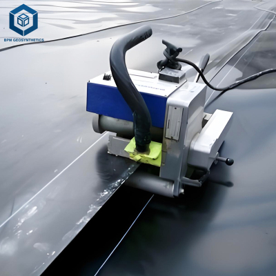
| Weldability | Excellent | Excellent (adjusted) | Good | Solvent weld |
| Chemical Resistance | Excellent | Excellent | Good | Moderate |
| Cost | Lower | 5–15% higher | Higher | Higher |
In textured vs smooth HDPE geomembrane for slope stability decisions, textured variants dominate steep containment systems.
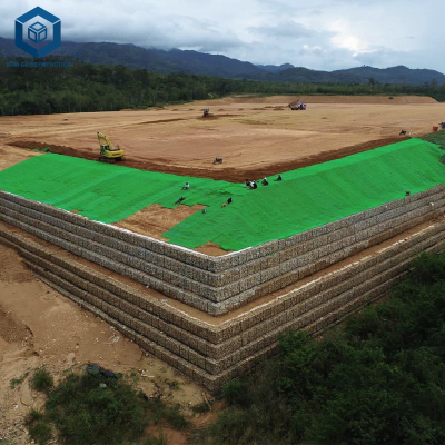
Application Scenarios
EPC Contractors
Landfill side slopes, heap leach pads, tailings dams.
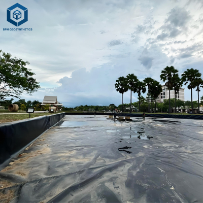
Developers
Water reservoirs with embankment slopes exceeding 18°.
Distributors / Importers
Stocking both types allows response to municipal and mining tenders.
Core Pain Points and Engineering Solutions
Slope Sliding Risk
Solution: Use textured vs smooth HDPE geomembrane for slope stability analysis with direct shear testing.Installation Difficulty on Steep Angles
Solution: Anchor trench design + double-sided textured liner.Interface Weakness with Geotextile
Solution: Laboratory interface friction testing under project load conditions.Long-Term Creep Concerns
Solution: Select ≥1.5 mm thickness and verify stress crack resistance.
Risk Warnings and Mitigation
Ignoring interface shear testing may lead to translational failure.
Over-texturing may reduce welding efficiency.
Insufficient anchor trench depth increases pullout risk.
Using smooth liners on slopes >20° without analysis is unsafe.
Procurement and Selection Guide
Define slope gradient and height.
Calculate required interface friction angle.
Request laboratory shear test reports.
Confirm asperity height specifications.
Verify compliance with GRI-GM13 or equivalent.
Assess welding procedure compatibility.
Review roll dimensions for installation logistics.
Evaluate lifecycle cost, not only material price.
The decision in textured vs smooth HDPE geomembrane for slope stability should always follow engineering calculations.
Engineering Case Example
Project: Copper Heap Leach Pad
Location: Semi-arid mining region
Slope: 1V:2.5H (≈21.8°)
Design Load: 250 kPa
Selected Material: 2.0 mm double-sided textured HDPE geomembrane
Interface Friction Angle Achieved: 27° (tested)
Outcome: Stable operation after 5+ years, no liner displacement.
This project confirms that textured vs smooth HDPE geomembrane for slope stability must be verified through testing rather than assumption.
FAQ
1. Is textured always required for slopes?
No. Mild slopes may perform adequately with smooth liners.
2. Does texturing reduce tensile strength?
No significant reduction when properly manufactured.
3. Can smooth liners be used with anchor systems?
Yes, but interface friction must still be verified.
4. Is cost difference significant?
Typically 5–15% depending on thickness.
5. Are both types chemically resistant?
Yes, identical polymer base.
6. What thickness is recommended for slopes?
Usually ≥1.5 mm for structural stability.
7. Can textured liners be welded normally?
Yes, with adjusted welding parameters.
8. Is double-sided texture necessary?
For soil-to-liner and liner-to-geotextile interfaces, often yes.
9. How to verify friction angle?
Direct shear testing under site-specific loads.
10. What standards apply?
GRI-GM13 and project-specific technical specifications.
Request Technical Support
For engineering drawings, laboratory reports, or project-specific recommendations regarding textured vs smooth HDPE geomembrane for slope stability, please request:
Technical data sheets
Interface shear test reports
Project sample rolls
Formal quotation
All inquiries are handled by technical engineers with slope containment experience.
Authoritative Engineering Statement (E-E-A-T)
This article is prepared by a geosynthetics technical team with over 10 years of field experience in landfill, mining, and water containment projects. All parameters are based on internationally recognized geomembrane standards and verified engineering practice.
For critical infrastructure projects, independent geotechnical verification is recommended.