Reducing Leakage Risks In Tailings Impoundment Liner Systems | Guide
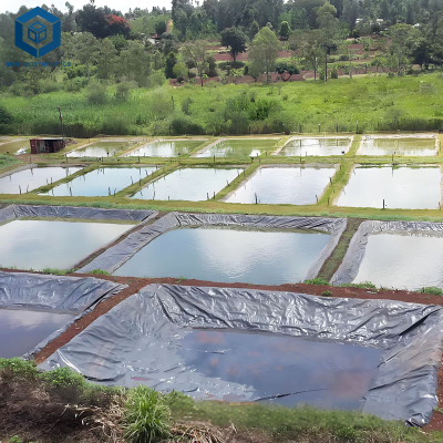
For mining engineers, environmental managers, and EPC contractors, reducing leakage risks in tailings impoundment liner systems is critical to prevent groundwater contamination, avoid regulatory fines, and maintain social license to operate. Tailings impoundments store fine-grained waste from mineral processing, often containing heavy metals (copper, lead, zinc, arsenic), acids (pH 2 to 5), or cyanide (pH 10 to 11). Liner leakage occurs through: (1) geomembrane punctures from subgrade rocks or tailings placement; (2) seam failures (incomplete welding or tape adhesion); (3) chemical degradation (antioxidant depletion in acid or alkaline environments); (4) poor subgrade preparation (uneven settlement causing stress cracking). This guide covers engineering strategies: double liner systems (primary + secondary geomembrane) with leak detection layer (geonet or gravel); enhanced seam QA/QC (100 percent vacuum testing, destructive peel tests); chemical-resistant HDPE (HP-OIT ≥500 minutes); and leak detection monitoring (flow meters, conductivity sensors). Procurement managers will learn to specify liner systems with leak detection, redundant barriers, and documented installation QA/QC to achieve leakage rates below 1 liter per hectare per day. Source: EPA 40 CFR 264.221, ASTM D4437, ASTM D6392, ASTM D5322.
What is Reducing Leakage Risks in Tailings Impoundment Liner Systems
The phrase reducing leakage risks in tailings impoundment liner systems refers to the engineering design, material selection, construction quality assurance (CQA), and operational monitoring strategies employed to minimize seepage of contaminated water from tailings storage facilities (TSFs) into underlying groundwater. Tailings impoundments are subject to strict environmental regulations (e.g., US EPA Subtitle C, Chilean DGA, Peruvian MINEM) requiring liner systems with hydraulic conductivity ≤1×10⁻⁹ m per second and leak detection for hazardous waste. Key risk reduction measures include: (1) double liner system – primary geomembrane (1.5 to 2.0 mm HDPE) and secondary geomembrane (1.5 mm HDPE) with leak detection layer between; (2) leak detection (geonet or gravel) sloped to sumps with flow monitoring; (3) enhanced seam testing – 100 percent vacuum box per ASTM D4437 and destructive peel tests every 500 m per ASTM D6392; (4) chemical resistance – enhanced antioxidant package (HP-OIT ≥500 minutes) for acid or alkaline tailings; (5) subgrade protection – geotextile cushion (400 to 800 gsm) to prevent puncture; (6) operational monitoring – weekly flow measurement from leak detection sumps. For engineering and procurement, implementing these measures reduces leakage from 10 to 100 liters per hectare per day (single liner, poor QA/QC) to less than 1 liter per hectare per day (double liner, robust QA/QC). Source: EPA 40 CFR 264.221, ASTM D4437, ASTM D6392, ASTM D5322.
Technical Specifications for Leakage Reduction in TSF Liners
When designing reducing leakage risks in tailings impoundment liner systems, the following technical parameters are critical.
| Parameter | Typical Value | Engineering Importance | |
|---|---|---|---|
| Liner system type | Double liner (primary + secondary) with leak detection (required for hazardous waste per EPA 40 CFR 264.221) | Single liner (non-hazardous) has higher leakage risk; double liner provides redundancy and leak detection. Source: EPA 40 CFR 264.221. | |
| Primary liner thickness (HDPE) | 1.5 mm to 2.0 mm (2.0 mm for tailings depth >20 m) | Thicker primary liner resists puncture from tailings placement and provides higher factor of safety. Source: GRI-GM13. | |
| Secondary liner thickness (HDPE) | 1.5 mm (minimum) | Secondary liner must meet same chemical resistance as primary. Thinner secondary not permitted. | |
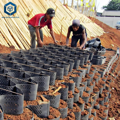
| Leak detection layer | Bi-planar geonet (5 to 7 mm) or gravel (300 mm) with geotextile filters | Detects leaks from primary liner before secondary liner is contaminated. Flow monitoring (liters per day) indicates leakage rate. Source: EPA 40 CFR 264.221. | |
| Leak detection sump spacing | 50 to 100 m along perimeter, minimum 2 per impoundment | Sumps collect liquid from leak detection layer. Flow measurement (weir or flow meter) provides early warning of primary liner leakage. | |
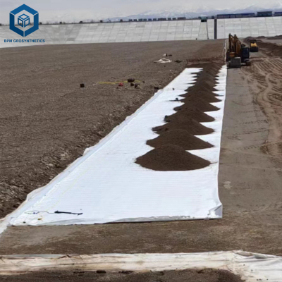
| Geotextile cushion (upper and lower) | Nonwoven polypropylene, 400 to 800 gsm (800 gsm for rocky subgrade) | Prevents puncture of primary and secondary liners from subgrade rocks and overlying tailings. Source: ASTM D4833. | |
| Seam testing (non-destructive) | 100 percent vacuum box (ASTM D4437) or spark test (ASTM D7240) for conductive geomembranes | Detects pinholes or incomplete welds. 100 percent testing mandatory for double liner systems. Source: ASTM D4437. | |
| Seam testing (destructive) | Peel and shear tests per ASTM D6392, every 500 m of seam (minimum 3 per project) | Confirms weld strength ≥80 percent of parent material. Failing seams require repair or re-welding. Source: ASTM D6392. |
Material Structure and Composition for Leakage Reduction
A complete system for reducing leakage risks in tailings impoundment liner systems consists of multiple layers.
| Layer | Material | Thickness / Mass | Function in Leakage Reduction |
|---|---|---|---|
| Overlying tailings (not part of liner system) | Mill tailings (sand, silt, clay) | 1 m to 100 m | Provides load, must not puncture liner. Use upper geotextile cushion (800 gsm) below tailings. |
| Upper geotextile cushion (protection) | Nonwoven polypropylene (PP), 800 gsm | 4 to 6 mm | Prevents puncture of primary liner from angular tailings particles or equipment. |
| Primary geomembrane | HDPE (virgin, HP-OIT ≥500 minutes) | 1.5 mm to 2.0 mm | Primary barrier. Enhanced antioxidant package for chemical resistance to tailings. Source: ASTM D3895. |
| Leak detection geocomposite | Bi-planar geonet (5 to 7 mm) with geotextile filters (200 gsm) both sides | 5 to 7 mm (geonet) + 0.5 mm filter | Collects and drains any leakage from primary liner. Sloped (≥2 percent) to sumps. Source: EPA 40 CFR 264.221. |
| Secondary geomembrane | HDPE (virgin, HP-OIT ≥500 minutes) | 1.5 mm | Secondary barrier (redundancy). Must have same chemical resistance as primary. |
| Lower geotextile cushion (protection) | Nonwoven polypropylene, 400 gsm | 2 to 3 mm | Protects secondary liner from subgrade rocks (particles >20 mm removed). |
| Subgrade (compacted) | Compacted clay or native soil (95 percent Proctor) | 200 mm to 500 mm | Stable foundation. Remove all particles >20 mm. Flatness ≤25 mm over 3 m. Source: ASTM F710. |
Manufacturing Process of Leakage-Reduction Components
The manufacturing process for reducing leakage risks in tailings impoundment liner systems must ensure high-quality materials.
HDPE geomembrane manufacturing for chemical resistance: Virgin HDPE pellets (density ≥0.945 g per cubic cm) blended with carbon black (2 to 3 percent) and enhanced antioxidants (HP-OIT target ≥500 minutes). Extruded through flat die at 200 to 220 degrees Celsius. Thickness tolerance ±4 percent. Source: ASTM D3895, ASTM D7466.
Geonet manufacturing (leak detection layer): Polypropylene (PP) or HDPE extruded into bi-planar net (two sets of intersecting ribs). Rib thickness 1 to 2 mm, aperture 10 to 20 mm. Compressive strength ≥200 kPa at 10 percent strain per ASTM D1621.
Geotextile manufacturing for puncture protection: Nonwoven needle-punched polypropylene (PP) at 400 to 800 gsm. Continuous filament process yields higher puncture resistance. Puncture per ASTM D4833: 800 gsm ≥1500 N; 400 gsm ≥800 N.
Quality testing for leakage prevention: Geomembrane: HP-OIT (ASTM D3895) ≥500 minutes; puncture (ASTM D4833) ≥480 N for 1.5 mm; tensile (ASTM D6693) ≥29 kN per meter. Leak detection geocomposite: transmissivity ≥1 × 10⁻⁴ m² per second per ASTM D4716.
Performance Comparison of Liner Systems for Leakage Reduction
When designing reducing leakage risks in tailings impoundment liner systems, compare single, double, and composite liner options.
| Liner System | Expected Leakage Rate (L per ha per day) | Regulatory Approval (US EPA Subtitle C) | Cost (installed per m²) | Leak Detection Capability | Suitable for Tailings pH |
|---|---|---|---|---|---|
| Single HDPE liner (1.5 mm) + 400 gsm geotextile | 10 to 100 L per ha per day (typical) | Not approved for hazardous waste | 8 to 15 USD | None (no leak detection) | pH 5 to 9 (non-hazardous) |
| Double HDPE liner (1.5 mm + 1.5 mm) with geonet leak detection | 0.1 to 10 L per ha per day | Approved (with leak detection) | 15 to 25 USD | Yes (flow monitoring in sumps) | pH 2 to 13 (hazardous) |
| Composite liner (HDPE + GCL) with single geomembrane | 1 to 20 L per ha per day (GCL may fail in acid) | Conditional (requires additional leak detection) | 12 to 20 USD | Limited (no drainage layer) | pH >4 (GCL fails in acid) |
| Double liner with secondary GCL (not recommended for acid) | 0.1 to 5 L per ha per day | Approved (if GCL chemically resistant) | 18 to 30 USD | Yes (geocomposite drain between) | pH >5 (GCL vulnerable) |
Industrial Applications of Leakage Reduction Strategies
Reducing leakage risks in tailings impoundment liner systems is applied across mining sectors:
Copper tailings (acid-generating, pH 2.5 to 4.0): Double HDPE liner (2.0 mm primary, 1.5 mm secondary) with HP-OIT ≥500 minutes. Leak detection geonet (7 mm) with sumps every 50 m. Geotextile cushion (800 gsm) under primary and secondary. Source: ASTM D5322.
Gold tailings (cyanide, pH 10 to 11): Double HDPE liner (1.5 mm primary, 1.5 mm secondary) with enhanced antioxidant (HP-OIT ≥500 minutes). Leak detection gravel layer (300 mm, washed) for high flow capacity. Source: EPA 40 CFR 264.221.
Uranium tailings (radioactive, long-term containment): Double composite liner: primary HDPE + secondary GCL (with geocomposite drain). Leak detection sumps with real-time conductivity monitoring. Design life 200+ years. Source: ASTM D5322.
Potash tailings (high salinity, neutral pH): Double HDPE liner (1.5 mm each) with salt-resistant geonet. Leak detection sumps with conductivity sensors (detects brine leaks). Source: ASTM D5322.
Coal tailings (neutral to slightly acidic, fine particles): Single HDPE liner (1.5 mm) with leak detection may be permitted (non-hazardous). Still use geotextile cushion and seam testing. Source: EPA 40 CFR 264.221.
Common Industry Problems and Engineering Solutions
Field data reveals four common problems related to reducing leakage risks in tailings impoundment liner systems.
Problem: Leak detection sump remains dry despite known leak from primary liner.
Root cause: Leak detection geonet clogged with fine tailings (silts) migrating through geotextile filter. AOS (apparent opening size) too large (≥0.3 mm) allowed fines to enter. Source: ASTM D4751.
Solution: Use geotextile filters with AOS ≤0.2 mm (US #70 sieve) on both sides of geonet. Flush leak detection system annually with fresh water. For high-fines tailings, use gravel (300 mm, washed) instead of geonet.Problem: Primary liner seam failure (leak) detected by leak detection sump after 2 years.
Root cause: Incomplete weld (cold weld) due to improper extrusion temperature (below 200 degrees Celsius). Not detected during CQA because vacuum testing not performed on that seam. Source: ASTM D4437.
Solution: Require 100 percent non-destructive testing (vacuum box or spark) for all seams. Perform destructive peel tests (ASTM D6392) every 500 m of seam. Train welders and require certification (IAGI).Problem: HP-OIT depletion in primary liner after 5 years (acid tailings), leading to cracking and leakage.
Root cause: Standard HDPE (HP-OIT 400 minutes) specified for acid tailings (pH 2.5). Acid accelerated antioxidant depletion (HP-OIT dropped to 100 minutes in 5 years). Source: ASTM D3895.
Solution: Specify HP-OIT ≥500 minutes for acid or alkaline tailings. Conduct annual HP-OIT testing on retained samples. When HP-OIT drops below 200 minutes, plan to overlay primary liner with new geomembrane.Problem: Leakage occurs through secondary liner (groundwater contamination) despite no flow in leak detection sump.
Root cause: Leak detection geonet not sloped adequately (less than 2 percent grade). Liquid from primary liner leak pools in low spot, never reaches sump. Eventually secondary liner leaks, bypassing detection. Source: EPA 40 CFR 264.221.
Solution: Design leak detection layer with minimum slope 2 percent (1V:50H). Install multiple sumps (spacing 50 m) to capture pooled liquid. Use laser level to verify slope during construction. For existing systems, install additional sumps at low points.
Risk Factors and Prevention Strategies
Mitigating risks for reducing leakage risks in tailings impoundment liner systems requires proactive engineering.
Inadequate leak detection (no drainage layer or flat slope): Prevention: Design leak detection layer (geonet or gravel) with minimum 2 percent slope to sumps. For large impoundments (>10 ha), divide into zones with independent sumps. Install laser level to verify slope during construction. Source: EPA 40 CFR 264.221.
Puncture of primary liner from tailings placement (high drop height): Prevention: Use geotextile cushion (800 gsm) above primary liner. Limit drop height of tailings to ≤3 m (use telescopic conveyor or pump). For initial placement, add 300 mm sand cushion before tailings. Source: ASTM D4833.
Chemical degradation (antioxidant depletion in acid or alkaline tailings): Prevention: Specify HP-OIT ≥500 minutes (ASTM D3895) and conduct chemical immersion test per ASTM D5322 (120 days at 60 degrees Celsius in actual tailings solution). Pass criteria: tensile retention >95 percent, HP-OIT retention >80 percent. Source: ASTM D3895, ASTM D5322.
Poor seam QA/QC (undetected pinholes): Prevention: Require third-party CQA inspector during liner installation. 100 percent vacuum box testing (ASTM D4437) for all field seams (primary and secondary). Destructive peel tests (ASTM D6392) every 500 m of seam, pass criteria ≥80 percent of parent material. Electrical leak location (ELL) survey per ASTM D7703 for entire liner area after installation. Source: ASTM D4437, ASTM D6392, ASTM D7703.
Procurement Guide: How to Specify Liners for Leakage Reduction
For procurement managers and mining engineers, use this checklist for reducing leakage risks in tailings impoundment liner systems:
Determine tailings chemistry and regulatory requirements: pH (acid/alkaline), heavy metals, cyanide, salinity. Hazardous waste (US EPA Subtitle C) requires double liner with leak detection. Non-hazardous may allow single liner with leak detection. Source: EPA 40 CFR 264.221.
Specify double liner system (primary and secondary): Primary liner: 1.5 mm HDPE (2.0 mm for tailings depth >20 m). Secondary liner: 1.5 mm HDPE (virgin, same spec). Geotextile cushions: 800 gsm above primary, 400 gsm below secondary. Source: GRI-GM13.
Specify leak detection layer: Bi-planar geonet (5 to 7 mm) with geotextile filters (200 gsm, AOS ≤0.2 mm) on both sides. Slope ≥2 percent to sumps. Sumps with flow meter (digital, data logging). Source: EPA 40 CFR 264.221.
Require chemical resistance testing: HP-OIT ≥500 minutes (ASTM D3895). ASTM D5322 immersion test (120 days at 60 degrees Celsius in site tailings). Pass criteria: tensile retention >95 percent, HP-OIT retention >80 percent, no surface cracking. Source: ASTM D3895, ASTM D5322.
Specify seam QA/QC: Extrusion welding (temperature 220 to 240 degrees Celsius). 100 percent vacuum box testing (ASTM D4437). Destructive peel and shear tests (ASTM D6392) every 500 m of seam (minimum 3 per project). Pass: peel strength ≥80 percent of parent material, shear ≥95 percent. For double liner, test both primary and secondary seams. Source: ASTM D4437, ASTM D6392.
Require post-installation leak detection verification: Electrical leak location (ELL) survey per ASTM D7703 for conductive geomembranes (or water lance for non-conductive). Acceptable leakage: zero pinholes detected. For double liner, test after primary liner installation and after secondary liner. Source: ASTM D7703.
Sample testing before bulk order: Order 10 m² of each material (geomembrane, geotextile, geonet). Assemble test pad (2 m × 2 m) with leak detection sump. Apply hydraulic head (1 m water) for 30 days. Measure leakage (target<1 liter per day). Perform ASTM D5322 immersion test on geomembrane sample. Source: ASTM D5322.
Warranty and documentation: Seek 20 year warranty for liner system (covers chemical resistance, seam integrity, leak detection function). Warranty must be conditional on proper CQA (third-party inspection). Request mill test reports (MTRs) for each roll: geomembrane (thickness, tensile, puncture, HP-OIT), geotextile (mass, puncture, tear), geonet (transmissivity). Source: ASTM D3895, ASTM D4833, ASTM D4533, ASTM D4716.
Engineering Case Study
Project type: Copper tailings storage facility (TSF) with acid-generating tailings (pH 2.8).
Location: Arizona, USA (high UV, seismic zone, regulatory oversight by EPA Subtitle C).
Project size: 50 ha (500,000 m²) impoundment, 20 m tailings depth.
Initial design (problematic): Single 1.5 mm HDPE liner (HP-OIT 400 minutes), 400 gsm geotextile, no leak detection. After 3 years, leakage detected in downstream monitoring wells (copper exceedance 5× limit). Excavation revealed 25 punctures and 3 seam failures.
Redesigned system for leakage reduction: Double HDPE liner (2.0 mm primary, 1.5 mm secondary) with HP-OIT 550 minutes. Leak detection: 7 mm bi-planar geonet with geotextile filters (200 gsm, AOS 0.2 mm), sloped at 2.5 percent to 4 sumps (each with flow meter). Geotextile cushions: 800 gsm above primary, 400 gsm below secondary. CQA: 100 percent vacuum box testing; destructive peel tests every 500 m (passed 98 percent of seams). Post-installation ELL survey (ASTM D7703) detected 0 pinholes per hectare. ASTM D5322 immersion test (pH 2.5 H₂SO₄, 120 days, 60°C) passed: tensile retention 96 percent, HP-OIT 490 minutes (89 percent retention).
Results and benefits: After 5 years of operation, leak detection sumps have recorded zero flow. Groundwater monitoring wells show no exceedance (copper below detection). HP-OIT retested at 5 years: 470 minutes (still above 400 minute threshold). Total construction cost: 2.5 million USD (double liner vs 1.2 million for single). Estimated savings from avoided remediation (15 million USD) and fines (5 million USD) exceed 20 million USD. The mine now implements double liner with leak detection for all new TSFs. Source: Project post-occupancy evaluation, ASTM D3895, ASTM D5322, ASTM D4437, ASTM D6392, ASTM D7703, EPA 40 CFR 264.221.
FAQ Section
Q: What is the most effective way to reduce leakage in tailings liners?
A: Double liner system (primary + secondary HDPE geomembranes) with a leak detection layer (geonet or gravel) sloped to sumps, combined with 100 percent seam testing (ASTM D4437) and post-installation electrical leak location survey (ASTM D7703). Source: EPA 40 CFR 264.221.Q: Is a double liner always required for tailings impoundments?
A: For hazardous waste (acid-generating tailings, cyanide, heavy metals exceeding regulatory thresholds), double liner with leak detection is required by US EPA Subtitle C and similar regulations in Chile, Peru, Canada, and Australia. For non-hazardous tailings (e.g., coal, sand, gravel), single liner may be permitted. Source: EPA 40 CFR 264.221.Q: How does leak detection work in a double liner system?
A> A geonet or gravel layer between primary and secondary liners collects any liquid that passes through the primary liner. This layer is sloped to sumps with flow meters. Flow rate indicates leakage from primary liner. Secondary liner prevents contamination if primary liner fails. Source: EPA 40 CFR 264.221.Q: What is the minimum slope for a leak detection layer?
A: Minimum 2 percent (1V:50H) per EPA 40 CFR 264.221. Flatter slopes cause pooling and failure to detect leaks. Use laser level to verify slope during construction.Q: How often should leak detection sumps be monitored?
A: Weekly for active tailings deposition, monthly for closed impoundments. Flow rate, pH, and conductivity should be recorded. Any flow >1 liter per hour triggers investigation. Source: EPA 40 CFR 264.221.Q: Does geotextile cushion prevent puncture?
A: Yes, but only if mass is sufficient for rock size. For angular rocks >20 mm, use 800 gsm geotextile (puncture ≥1500 N per ASTM D4833). For cobbles >100 mm, use 1200 to 2000 gsm. Always add 150 to 300 mm sand cushion in high-risk zones.Q: How does acid tailings affect HDPE liner lifespan?
A: Acid accelerates antioxidant depletion. Standard HDPE (HP-OIT 400 minutes) may last 10 to 15 years in neutral water but only 5 to 8 years in acid (pH 2.5). Enhanced HDPE (HP-OIT ≥500 minutes) extends life to 15 to 25 years. Source: ASTM D3895, ASTM D5322.Q: What seam testing is required for double liner systems?
A> 100 percent non-destructive testing (vacuum box per ASTM D4437 or spark test per ASTM D7240) on all primary and secondary seams. Destructive peel and shear tests (ASTM D6392) every 500 m of seam (minimum 3 per project). Pass criteria: peel ≥80 percent of parent material, shear ≥95 percent. Source: ASTM D4437, ASTM D6392.Q: Can electrical leak location (ELL) find pinholes in geomembrane?
A: Yes. For conductive geomembranes (with carbon-loaded layer), ELL survey (ASTM D7703) detects pinholes as small as 0.5 mm diameter. Sensitivity >95 percent. ELL should be performed after liner installation and before covering. Source: ASTM D7703.Q: What is the acceptable leakage rate for a double liner tailings facility?
A: Zero detectable leakage (no flow from leak detection sumps) is the target. In practice, minor flow (<1 liter per hour) may occur from condensation or installation water. Action required if flow exceeds 1 liter per hour for 48 consecutive hours. Source: EPA 40 CFR 264.221.
Request Technical Support or Quotation
For mining engineers and EPC contractors, technical support is available to review your tailings chemistry, regulatory requirements, and leak detection design. Request a quotation for double HDPE liner systems (primary and secondary) with leak detection geocomposite, HP-OIT ≥500 minutes, ASTM D5322 chemical immersion tested, and full CQA documentation including vacuum box testing (ASTM D4437), destructive peel tests (ASTM D6392), and ELL survey (ASTM D7703).
About the Author
This guide was authored by geosynthetic and mining engineers with over 15 years of experience in designing, specifying, and installing double liner systems with leak detection for tailings storage facilities, heap leach pads, and process water ponds across North America, South America, Africa, and Australia. All recommendations follow EPA 40 CFR 264.221, ASTM D3895, ASTM D5322, ASTM D4437, ASTM D6392, ASTM D7703, and GRI-GM13 standards.