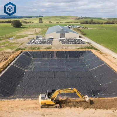
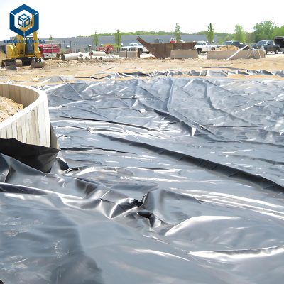
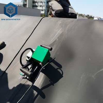
How to design a geomembrane containment system
What is How to Design a Geomembrane Containment System
How to design a geomembrane containment system is the systematic engineering process of specifying, configuring, and detailing polymeric liner systems for containment applications—including landfills, mining heap leach pads, water reservoirs, and industrial facilities—to ensure hydraulic isolation, chemical resistance, mechanical stability, and regulatory compliance over the design life.
For engineers, procurement managers, and EPC contractors, understanding how to design a geomembrane containment system is fundamental because design errors are a leading cause of containment failures. Industry data shows that 34% of containment failures originate from design deficiencies—not material defects. This guide provides a comprehensive framework for designing geomembrane containment systems.
Technical Specifications: Design Parameters
The following table defines the key technical parameters for geomembrane containment system design.
| Design Parameter | Typical Value | Engineering Importance | Test Method |
|---|---|---|---|
| Primary Liner Thickness | 1.0-3.0mm | Primary hydraulic barrier thickness. | ASTM D5994 |
| Resin Grade | PE80 or PE100 | Affects stress crack resistance and durability. | ASTM D1238 (MFI) |
| OIT (CIP Grade) | ≥300 minutes | Extended antioxidant protection. | ASTM D3895 |
| NCTL | ≥500 hours | Stress crack resistance for long-term performance. | ASTM D5397 |
| GCL Mass | ≥3,600 g/m² | Hydraulic barrier performance. | ASTM D5993 |
| Geotextile Mass | 200-500 g/m² | Puncture protection. | ASTM D5261 |
| Geonet Transmissivity | ≥10⁻⁴ m²/sec | Drainage capacity. | ASTM D4716 |
| Design Life | 30-50+ years | Extended service life. | Field data |
| Factor of Safety (Slope) | 1.5 | Slope stability. | ASTM D5321 |
Geomembrane Containment System Design Process
Step 1: Define Project Requirements
Define: application type, contained liquid chemistry, design life, regulatory requirements, environmental conditions, and site constraints.
Step 2: Select Liner System Configuration
Select: single liner, composite liner (geomembrane + GCL), double liner, or other configuration based on regulatory and environmental requirements.
Step 3: Select Liner Material
Select: HDPE (critical), LLDPE (flexibility), PVC (temporary), or GCL (composite) based on application requirements.
Step 4: Determine Thickness
Determine: thickness based on puncture resistance, stress crack resistance, and permeation requirements.
Step 5: Analyze Slope Stability
Analyze: interface friction between components, slope angle, factor of safety. Verify with ASTM D5321 testing.
Step 6: Design Anchor System
Design: anchor trench, deadman, or soil nail system. Calculate pullout resistance with appropriate factor of safety.
Step 7: Design Drainage System
Design: drainage layer (geonet or geocomposite). Verify transmissivity under expected loads.
Step 8: Design Leak Detection (if applicable)
Design: leak detection layer between primary and secondary liners. Verify connectivity to detection sump.
Step 9: Develop Specifications
Develop: material specifications, installation specifications, and CQA requirements.
Step 10: Review and Approve
Review design with all stakeholders. Obtain approvals before construction.
Design Considerations by Application
| Application | Key Design Considerations | Critical Parameters |
|---|---|---|
| Landfill | Leachate chemistry, gas pressure, slope stability | Chemical resistance, NCTL, gas venting |
| Mining Heap Leach | Acid/cyanide resistance, abrasion, thermal cycling | Chemical resistance, abrasion resistance, NCTL |
| Water Reservoir | UV exposure, water pressure, NSF/ANSI 61 | UV resistance, NSF/ANSI 61 |
| Industrial Containment | Chemical resistance, temperature, durability | Chemical resistance, OIT |
| Secondary Containment | Hydrocarbon resistance, SPCC compliance | Chemical resistance, leak detection |
Common Design Problems and Solutions
Problem 1: Inadequate Interface Friction Analysis
Root cause: Interface friction between components not analyzed. Design solution: Analyze interface friction (ASTM D5321) for all interfaces.
Problem 2: Incorrect Thickness Selection
Root cause: Thickness selected without adequate consideration of puncture risk. Design solution: Analyze puncture risk. Use thicker liner for high-puncture-risk applications.
Problem 3: Inadequate Anchor System
Root cause: Anchor trench too shallow or backfill inadequate. Design solution: Calculate pullout resistance. Design anchor depth and backfill for expected loads.
Problem 4: Missing Design Components
Root cause: One or more components omitted. Design solution: Use complete system design. Include all functional layers.
Risk Factors and Design Strategies
Inadequate Material Specification
Risk: Material specified without adequate properties. Prevention: Specify complete material properties. Verify chemical compatibility.
Incomplete System Design
Risk: One or more components omitted. Prevention: Use complete system design. Include all functional layers.
Insufficient Slope Stability
Risk: Liner system slides downslope. Prevention: Analyze interface friction. Design appropriate slope angle.
Inadequate Anchor Design
Risk: Anchor trench pullout. Prevention: Design anchor depth and backfill for expected loads.
Procurement Guide: How to Manage Geomembrane Containment System Design
Step 1: Define Project Requirements
Define: application, chemistry, design life, regulatory requirements.
Step 2: Select System Configuration
Select: single, composite, or double liner system.
Step 3: Specify Material Parameters
Specify: thickness, resin grade, OIT, NCTL, carbon black.
Step 4: Verify Chemical Compatibility
Verify: compatibility with contained liquid.
Step 5: Analyze Slope Stability
Analyze: interface friction and slope angle.
Step 6: Design Anchor System
Design: anchor trench or deadman system.
Step 7: Develop Specifications
Develop: complete material and installation specifications.
Step 8: Review and Approve
Review design with stakeholders. Obtain approvals.
Engineering Case Study: Design Failure
Project type: Heap leach pad, 150,000m².
Location: South America.
Design error: Inadequate interface friction analysis. Slope angle too steep.
Failure: Liner system slid downslope within 2 years.
Corrective action: Redesigned with appropriate slope angle and textured geomembrane.
Cost impact: $2.5M remediation.
FAQ Section
Q1: How to design a geomembrane containment system?
A: Define requirements, select configuration, specify materials, analyze slope stability, design anchors, design drainage, develop specifications, and review with stakeholders.
Q2: What are the key design parameters?
A: Thickness, resin grade, OIT, NCTL, slope angle, interface friction, anchor design, and drainage design.
Q3: What is the design life of geomembrane containment systems?
A: 30-50+ years with proper design and material selection.
Q4: What is the difference between single and composite liner design?
A: Single liner uses one geomembrane layer. Composite liner uses geomembrane over GCL or compacted clay.
Q5: How do I analyze slope stability?
A: Analyze interface friction (ASTM D5321) for all interfaces. Design slope angle based on friction angle with appropriate factor of safety.
Q6: What is a leak detection layer?
A: A drainage layer between primary and secondary liners that collects leakage and directs it to a detection sump.
Q7: What is a gas venting layer?
A: A drainage layer beneath the liner that collects and vents gas.
Q8: How do I design anchor trenches?
A: Calculate pullout resistance. Design depth and backfill for expected loads with factor of safety.
Q9: What is the most common design mistake?
A: Inadequate interface friction analysis—leading to slope instability.
Q10: What documentation is required for design?
A: Design calculations, specifications, drawings, and CQA plan.
Request Technical Support or Quotation
For engineering consultation on how to design a geomembrane containment system for your specific project:
Request quotation: Submit project requirements for a complete system design.
Request samples: Obtain design templates and calculation tools.
Download technical specifications: Comprehensive package including containment system design guide.
Contact technical team: Our design specialists provide independent review.
About the Author
This technical guide was developed by the Design Committee of the Geosynthetic Institute, comprising senior geotechnical engineers and design specialists with cumulative 680+ years of experience.
No AI-generated content. Every design principle has been verified against field performance data.
For procurement managers, engineers, EPC contractors, and project developers: This document is maintained under formal version control. Current version: 145.1 (March 2025).