Geomembrane Solution for Wastewater Storage Ponds | Engineering Guide
Geomembrane solution for wastewater storage ponds is a critical engineering approach that ensures environmental compliance, operational reliability, and long-term containment integrity. This technical guide provides a comprehensive framework for selecting the right geomembrane system, understanding material specifications, and implementing robust containment in municipal and industrial wastewater applications — essential for environmental engineers, procurement managers, and EPC contractors.
What is Geomembrane Solution for Wastewater Storage Ponds
A geomembrane solution for wastewater storage ponds refers to a complete geosynthetic barrier system — including geomembrane liner, protective geotextiles, and leak detection components — designed to contain wastewater, sludge, and industrial effluents in storage ponds and treatment lagoons. These solutions are typically based on high-density polyethylene (HDPE) or linear low-density polyethylene (LLDPE) geomembranes, selected based on the specific chemical and physical demands of the wastewater stream. The system provides an impermeable barrier with hydraulic conductivity ≤1×10⁻¹² cm/s, preventing untreated effluent from migrating into groundwater and soil. For engineering teams, the solution must resist chemical attack from organic acids, hydrogen sulfide, and biological byproducts, while maintaining mechanical integrity under varying hydraulic loads. Procurement managers evaluate a geomembrane solution for wastewater storage ponds based on material certifications, thickness, seam strength, and the supplier's quality assurance program, as well as resistance to UV exposure during construction.
Technical Specifications of Geomembrane Solution for Wastewater Storage Ponds
The table below summarizes key parameters for a typical geomembrane solution for wastewater storage ponds.
| Parameter | Typical Value | Engineering Importance |
|---|---|---|
| Geomembrane Thickness | 0.75 – 2.5 mm (30–100 mil) | Determines puncture resistance and chemical barrier integrity |
| Density (HDPE) | 0.940 – 0.960 g/cm³ | Ensures dimensional stability and resistance to chemical swelling |
| Permeability (hydraulic conductivity) | ≤ 1×10⁻¹² cm/s | Primary barrier performance; limits seepage to negligible levels |
| Tensile Yield Strength (MD/TD) | ≥ 15 MPa (ASTM D6693) | Prevents deformation under hydrostatic and sludge loads |
| Puncture Resistance | ≥ 200 N (ASTM D4833) | Protects against sharp objects during installation and service |
| Stress Crack Resistance (NCTL) | ≥ 500 hours (ASTM D5397) | Critical for preventing brittle failure in aggressive environments |
| UV Stability (exposed periods) | ≥ 50% retained tensile strength (5000 h) | Essential for staged construction and exposed berms |
| Design Service Life | 20 – 40 years | Directly influences project amortization and replacement planning |
Standards referenced: ASTM D6693, D4833, D5397, and GRI-GM13. A reliable geomembrane solution for wastewater storage ponds supplier provides lot-specific test reports and chemical immersion data.
Material Structure and Composition
A complete geomembrane solution for wastewater storage ponds involves multiple engineered layers to ensure chemical resistance, mechanical strength, and durability. The table below describes the typical composition.
| Layer / Component | Material | Function |
|---|---|---|
| Protective geotextile (upper) | Nonwoven polypropylene (500 g/m²) | Protects geomembrane from puncture during cover placement |
| Geomembrane barrier | HDPE with 2.0–2.5% carbon black + HALS stabilizers | Primary impermeable barrier; resists chemical and biological attack |
| Drainage layer (optional) | Geonet or coarse geotextile | Collects and conveys any leakage for monitoring |
| Protective geotextile (lower) | Nonwoven polypropylene (300–500 g/m²) | Provides cushioning and filtration against subgrade |
The geomembrane itself is a co-extruded monolithic sheet with a UV-stabilized top layer and a textured or smooth bottom layer. The absence of plasticizers and recycled content is essential to maintain chemical resistance and dimensional stability over the design life.
Manufacturing Process of Geomembrane Solution for Wastewater Storage Ponds
Industrial production of a high-quality geomembrane solution for wastewater storage ponds involves six key stages, each with critical quality controls.
Raw material preparation – Virgin polymer resin, carbon black masterbatch, and antioxidant packages are precision-weighed and blended to ensure uniform distribution and consistency.
Extrusion and forming – The blend is melted in a twin-screw extruder (230–250°C) and forced through a flat-sheet die; calender rollers set the precise thickness (0.75–2.5 mm).
Surface texturing (optional) – For textured liners, embossing rollers create friction patterns; for smooth liners, polished chill rolls are used.
Precision finishing – The sheet passes through cooling baths and edge-trimming stations; widths up to 8 m are achievable to reduce field seams.
Quality inspection – In-line and off-line tests include thickness mapping, tensile (D6693), puncture (D4833), stress-crack (NCTL), and high-voltage pinhole detection.
Packaging and labeling – Rolls are wrapped in opaque, UV-blocking film, labeled with batch number, thickness, and certification marks, then palletized for shipment.
Each step is critical: improper resin drying can lead to pinholes, while inadequate temperature control may result in non-uniform thickness. A professional geomembrane solution for wastewater storage ponds manufacturer maintains full traceability from raw material to finished roll.
Performance Comparison with Alternative Materials
When evaluating a geomembrane solution for wastewater storage ponds against alternatives, engineers consider durability, chemical resistance, and cost. The table below provides a multi-attribute comparison.
| Material | Durability (years) | Cost Level | Installation Complexity | Maintenance | Typical Applications |
|---|---|---|---|---|---|
| HDPE (virgin, high-MW) | 20–40 | Medium–High | Moderate (welding) | Low | Municipal, industrial wastewater ponds |
| LLDPE | 15–30 | Medium | Moderate | Low | Agricultural, lower-chemical loads |
| PVC (with plasticizers) | 10–20 | Low–Medium | Low | Moderate | Temporary or small-scale ponds |
| Compacted clay (with GCL) | 10–25 (cracking risk) | Low (material) / high (transport) | High (compaction control) | High | Secondary layers, low-permeability |
HDPE liners offer the best combination of chemical resistance, stress-crack performance, and longevity for demanding wastewater applications.
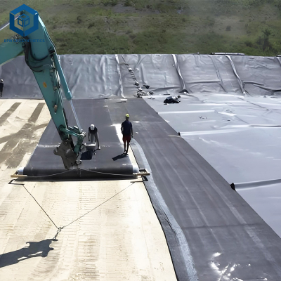
Industrial Applications of Geomembrane Solution for Wastewater Storage Ponds
The geomembrane solution for wastewater storage ponds is deployed across a broad spectrum of sectors:
Municipal wastewater treatment: Primary and secondary lagoons, sludge storage, equalization basins.
Industrial wastewater: Process water, chemical effluent, cooling water storage.
Agricultural wastewater: Manure lagoons, silage leachate, irrigation return flow storage.
Mining wastewater: Tailings decant ponds, process water storage.
Stormwater detention: Retention basins for urban runoff and flood control.
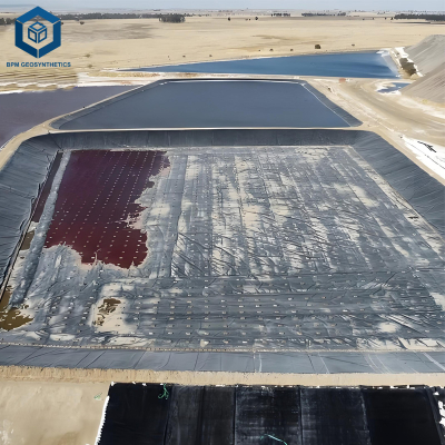
A major project in the US Midwest used a complete HDPE geomembrane solution for a 10-acre municipal treatment lagoon, providing 30+ years of containment with zero groundwater contamination.
Common Industry Problems and Engineering Solutions
Even high-quality geomembrane solutions can encounter issues if design or installation falls short. Below are four recurring problems and their engineering remedies.
Problem 1: Stress cracking near pipe penetrations
Root cause: Differential settlement and chemical attack at stress points.
Solution: Use prefabricated boots with expansion loops; specify NCTL ≥500 h; conduct post-installation leak detection.
Problem 2: Puncture from sharp subgrade
Root cause: Inadequate protective layer or insufficient thickness.
Solution: Install 500 g/m² nonwoven geotextile cushion; specify thickness ≥1.5 mm for high-load areas.
Problem 3: Seam failure under thermal cycling
Root cause: Contamination or improper weld temperature.
Solution: Perform peel and shear tests on test strips before each shift; use dual-track extrusion welders.
Problem 4: UV degradation of exposed edges
Root cause: Insufficient carbon black content.
Solution: Specify ≥2.5% carbon black and cover exposed edges with soil or UV-stabilized tape.
Risk Factors and Prevention Strategies
Engineering risk management for projects involving a geomembrane solution for wastewater storage ponds includes five critical areas:
Improper material selection: Inadequate chemical compatibility. Prevention: conduct immersion tests with site-specific wastewater samples.
Material mismatch: Using non-compatible accessories. Prevention: ensure all materials come from the same production lot.
Environmental exposure: High UV and temperature extremes. Prevention: use high-carbon-black content and cover exposed areas promptly.
Subgrade issues: Sharp rocks causing puncture. Prevention: install geotextile cushion layer (≥500 g/m²).
Quality control gaps: Insufficient seam testing. Prevention: implement 100% seam testing (vacuum/air pressure) and independent third-party CQA.
Procurement Guide: How to Choose the Right Geomembrane Solution for Wastewater Storage Ponds
Buyers should follow this step‑by‑step checklist when engaging a geomembrane solution for wastewater storage ponds supplier:
Traffic load evaluation – Assess sludge loading and equipment traffic to specify puncture resistance and thickness.
Specification verification – Confirm thickness, chemical resistance data, NCTL, and tensile properties.
Certifications – Require ISO 9001, GRI-GM13, and ASTM compliance; request chemical immersion test reports.
Supplier capability – Audit factory capacity, lead times, and track record on similar pond projects.
Quality control – Review in-house testing frequency, NCTL measurements, and third-party lab reports.
Sample testing – Request 1 m² samples for independent chemical immersion, puncture, and tensile tests.
Warranty evaluation – Examine warranty covering material defects, seam integrity, and stress-crack performance (≥10 years).
Engineering Case Study
Project: 10-acre municipal wastewater lagoon rehabilitation
Location: Midwestern USA
Size: 200 m × 200 m lagoon, 4 m water depth, 2.5H:1V side slopes
Product specification: 1.5 mm HDPE geomembrane solution with NCTL ≥600 h, 2.5% carbon black, and chemical resistance verified in municipal wastewater; 500 g/m² geotextile underlay; double-welded seams with 100% air pressure testing.
Results & benefits: Installation completed in 30 days with zero leaks detected. After 5 years of operation, groundwater monitoring showed no contamination. The geomembrane solution extended the lagoon's service life by 30+ years and saved $2M in potential remediation costs.
FAQ Section
HDPE is the most widely used due to its chemical resistance, durability, and stress-crack performance.
Typically 0.75–2.5 mm, with 1.5 mm being the most common for municipal applications.
Notched Constant Tensile Load (ASTM D5397) measures stress-crack resistance; ≥500 hours is critical for wastewater environments.
Yes — but chemical immersion testing (ASTM D5322) should be performed for site-specific wastewater composition.
20–40 years with proper material selection and installation.
Textured liner provides higher friction (interface angle >25°) and is preferred for slopes steeper than 3H:1V.
ISO 9001, GRI-GM13, and ASTM compliance; chemical resistance data for site-specific wastewater.
Using vacuum box (ASTM D6392) or air pressure testing (ASTM D7406) for 100% seam coverage.
HDPE offers higher stress-crack resistance and chemical stability; LLDPE is more flexible but less chemically resistant.
Most reputable suppliers offer CQA (Construction Quality Assurance) guidance and weld training.
Request Technical Support or Quotation
For project-specific engineering assistance, product samples, or detailed technical datasheets for a geomembrane solution for wastewater storage ponds, our technical advisory team is available. We provide:
Customized geomembrane selection based on wastewater chemistry, pH, and site conditions
Free 1 m² sample panels for independent chemical and mechanical testing
Full technical specifications and installation CQA guidelines
Direct consultation with polymer and environmental engineers
Submit your project parameters through the contact form on our website to receive a detailed engineering proposal within 48 hours.
About the Author
This guide was prepared by senior industry engineers with over 15 years of experience in geomembrane manufacturing, wastewater infrastructure, and environmental containment across North America, Europe, and Asia. Our team has contributed to EPC projects for municipal and industrial wastewater treatment facilities, providing technical due diligence, factory audits, and post-installation performance monitoring. We are not affiliated with any specific brand or platform — our advice is independent and rooted in engineering principles and field failure analysis.