Geomembrane Slope Installation Problem: Engineering Guide
What is Geomembrane Slope Installation Problem?
Geomembrane slope installation problem refers to the common failures and difficulties encountered when placing HDPE or LLDPE geomembranes on sloped subgrades (typically > 3H:1V) for landfill liners, mining heap leach pads, and pond embankments. For civil engineers, EPC contractors, and procurement managers, understanding geomembrane slope installation problems is critical because slopes magnify installation challenges: panel sliding during deployment, wrinkle formation from tension mismatch, seam alignment difficulties, and inadequate anchorage. These problems lead to stress cracking, reduced service life, and containment failure. Common geomembrane slope installation problems include: panel slippage (insufficient friction between geomembrane and subgrade), wrinkles (thermal expansion or improper tensioning), seam misalignment (panel drift), and anchor trench pullout. This guide provides engineering analysis of geomembrane slope installation problems: prevention strategies (textured geomembrane, proper tensioning, deployment techniques), slope length limits, and QA/QC procedures for landfill side slopes, heap leach pads, and reservoir embankments.
Technical Specifications Related to Geomembrane Slope Installation Problem
The table below defines critical parameters for slope installation per GRI GM17 and ASTM standards.
| Parameter | Standard Value / Practice | Engineering Importance |
|---|---|---|
| Maximum Slope Angle (smooth geomembrane) | ≤ 3H:1V (18°) without geotextile friction layer | Steeper slopes cause sliding — a primary geomembrane slope installation problem.}, |
| Maximum Slope Angle (textured geomembrane) | ≤ 2H:1V (27°) to 1.5H:1V (34°) | Textured increases interface friction angle (φ = 18°–30° vs. 8°–14° for smooth).}, |
| Panel Deployment Direction | Parallel to slope (top to bottom) — never perpendicular | Perpendicular deployment causes excessive wrinkling and seam stress.}, |
| Wrinkle Height Limit | ≤ 25 mm (1 inch) — any wrinkle > 25 mm must be repaired | Wrinkles create stress concentration points → cracking.}, |
| Panel Tension During Deployment | Manual tensioning or mechanical winch (≤ 2% elongation) | Insufficient tension causes wrinkles; excessive tension tears geomembrane.}, |
| Anchor Trench at Slope Crest | Depth ≥ 0.9 m, embedment ≥ 0.75 m for slopes > 3H:1V | Prevents liner pullout — critical for steep slopes.}, |
| Geotextile Cushion (under geomembrane) | Nonwoven ≥ 300 g/m² (500 g/m² for sharp subgrade) | Reduces puncture risk and increases friction.}, |
| Slope Length Limit (without intermediate anchorage) | ≤ 30 m (100 ft) for smooth; ≤ 50 m for textured | Longer slopes require bench anchors or intermediate trenches.}, |
Key takeaway: Geomembrane slope installation problems are preventable with textured geomembrane (for slopes > 3H:1V), proper tensioning, panel deployment parallel to slope, and adequate anchor trenches.
Material Structure and Composition: How Geomembrane Properties Affect Slope Installation
Understanding material properties helps prevent geomembrane slope installation problems.
| Property | Effect on Slope Installation | Failure Mode if Inadequate |
|---|---|---|
| Surface Texture (smooth vs. textured) | Textured increases interface friction (φ = 18°–30°) | Smooth geomembrane slides on steep slopes → panel drift, seam stress.}, |
| Tensile Strength (ASTM D6693) | Higher strength resists tension during deployment | Low strength tears under winch tensioning.}, |
| Elongation at Break | ≥ 700% allows stretching without tearing | Brittle material cracks under slope tension.}, |
| Coefficient of Thermal Expansion | HDPE expands/contracts ~0.2 mm/m/°C | Temperature changes cause wrinkles or tension increase.}, |
Engineering insight: Geomembrane slope installation problems are minimized by using textured geomembrane on slopes > 3H:1V. Smooth geomembrane is limited to ≤ 3H:1V slopes.
Manufacturing Process: How Geomembrane Quality Affects Slope Installation
Factory quality directly influences slope installation success.
Resin compounding: Consistent carbon black dispersion ensures uniform thermal expansion — reduces wrinkling.
Extrusion: Thickness variation (±10%) affects tension distribution during slope deployment.
Surface texturing (for textured geomembrane): Consistent texture depth (0.25–0.75 mm) ensures predictable friction angle.
Roll winding: Tightly wound rolls may have curvature that affects panel alignment on slopes.
Roll width: Wider rolls (7–8 m) reduce number of slope seams but are heavier to deploy.
Quality documentation: Friction angle test reports (ASTM D5321) essential for slope stability design.
Procurement insight: For projects with steep slopes, specify textured geomembrane with documented interface friction angle (≥ 22° for slopes > 2H:1V).
Performance Comparison: Slope Installation Methods for Geomembranes
Comparing different approaches to prevent geomembrane slope installation problems.
| Installation Method | Max Slope Angle | Wrinkle Control | Installation Speed | Typical Applications | |
|---|---|---|---|---|---|
| Smooth HDPE, no tensioning | ≤ 3H:1V | Poor (many wrinkles) | Fast | Flat areas only — not for slopes}, | |
| Smooth HDPE + mechanical tensioning | ≤ 3H:1V | Fair | Medium | Gentle slopes, small areas}, | |
| Textured HDPE + manual tensioning | ≤ 2H:1V | Good | Medium | Landfill side slopes, mining pads}, | |
| Textured HDPE + winch tensioning | ≤ 1.5H:1V | Excellent | Slow | Steep slopes, large areas}, |
Conclusion: Geomembrane slope installation problems are best addressed with textured HDPE and mechanical tensioning for slopes > 3H:1V.
Industrial Applications and Geomembrane Slope Installation Problem Risks
Different slope applications have specific installation challenges.
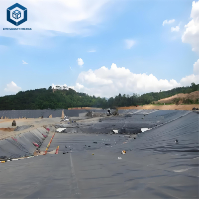
Landfill side slopes (3H:1V to 2H:1V): Textured HDPE required. Panel deployment parallel to slope. Wrinkle management critical.
Mining heap leach pads (steep slopes, 2H:1V to 1.5H:1V): Textured HDPE with winch tensioning. Bench anchors at mid-slope.
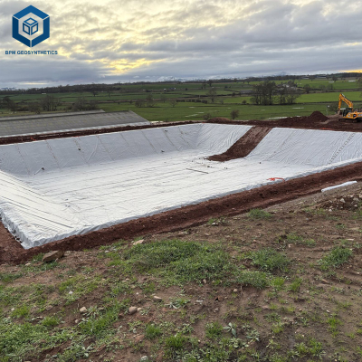
Pond embankments (3H:1V to 4H:1V): Smooth HDPE may be acceptable with proper tensioning. Geotextile cushion recommended.
Reservoir slopes (variable): For slopes > 3H:1V, specify textured geomembrane to prevent sliding.
Canal liners (side slopes, 2H:1V): Textured HDPE or LLDPE. Shorter panel lengths (≤ 50 m) to reduce tension.
Common Geomembrane Slope Installation Problems and Engineering Solutions
Real-world failures from improper slope installation.
Problem 1: Panel sliding downslope during deployment (most common)
Root cause: Smooth geomembrane on slope > 3H:1V with insufficient friction. Panel slides under its own weight. Solution: Use textured geomembrane (φ = 18°–30°). Temporary anchorage at top with sandbags or pins. This is the most frequent geomembrane slope installation problem.
Problem 2: Wrinkles across slope (perpendicular to drainage direction)
Root cause: Panel deployed perpendicular to slope direction (horizontal rolling). Thermal expansion creates buckles. Solution: Always deploy panels parallel to slope (top to bottom). Tension panels during deployment. This geomembrane slope installation problem is preventable with correct deployment orientation.
Problem 3: Seam misalignment at slope (panel drift)
Root cause: Uneven tension between adjacent panels. One panel slides more than the other. Solution: Use consistent tensioning for all panels. Align seams before welding. Install temporary anchors at panel edges.
Problem 4: Anchor trench pullout at slope crest
Root cause: Trench too shallow (< 0.6 m) or embedment too short (< 0.5 m) for slope tension. Solution: For slopes > 3H:1V, trench depth ≥ 0.9 m, embedment ≥ 0.75 m. Use concrete deadman for steep slopes (> 2H:1V).

Risk Factors and Prevention Strategies for Geomembrane Slope Installation Problems
Risk: Installing smooth geomembrane on steep slope (> 3H:1V): Panel slides, wrinkles, seam failure. Mitigation: For slopes > 3H:1V, specify textured geomembrane. Perform interface friction test (ASTM D5321) with site-specific subgrade.
Risk: No tensioning during deployment: Wrinkles form, leading to stress cracking. Mitigation: Use winch or manual tensioning to keep panel taut. Target ≤ 2% elongation.
Risk: Long slope without intermediate anchorage: Excessive tension at bottom of slope. Mitigation: For slope length > 30 m (smooth) or > 50 m (textured), install bench anchors or intermediate anchor trenches.
Risk: Poor weather conditions (high wind, rain): Wind lifts panels; rain reduces friction. Mitigation: Do not install in wind > 25 km/h. Place temporary sandbags on deployed panels.
Procurement Guide: How to Specify for Geomembrane Slope Installation
Follow this 8-step checklist for B2B purchasing decisions to prevent geomembrane slope installation problems.
Determine slope angle and length: For slopes > 3H:1V, require textured geomembrane. Calculate tension forces.
Specify geomembrane surface texture: Single-sided textured (friction against cover soil) or double-sided (friction both sides).
Require interface friction test (ASTM D5321): Minimum φ = 18° for slopes > 3H:1V. Verify with site-specific subgrade and geotextile.
Specify deployment direction: Panels must be deployed parallel to slope (top to bottom). Include in installation drawings.
Require tensioning procedure: Winch or manual tensioning with target elongation ≤ 2%. Document tension force.
Specify anchor trench dimensions: Depth ≥ 0.9 m, embedment ≥ 0.75 m for slopes > 3H:1V. For slopes > 2H:1V, require concrete deadman.
Order pre-installation slope mockup: Install 10 m × 10 m test panel on representative slope. Verify wrinkle control and seam alignment.
Include QA/QC hold points: Verify subgrade flatness, anchor trench dimensions, panel tension, and wrinkle removal before welding.
Engineering Case Study: Geomembrane Slope Installation Problem in Landfill Side Slope
Project type: Landfill side slope (2.5H:1V, 22°).
Location: Central Europe.
Project size: 25,000 m² of slope area.
Initial problem: Contractor attempted to install smooth 1.5 mm HDPE. Panels slid downslope during deployment. Wrinkles formed across slope. Seams misaligned by up to 300 mm.
Geomembrane slope installation problem analysis: Smooth HDPE interface friction (φ = 12°) insufficient for 22° slope. No tensioning used. Panels deployed perpendicular to slope.
Remediation: Replaced smooth HDPE with single-sided textured HDPE (φ = 22°). Deployed panels parallel to slope (top to bottom) with winch tensioning (1,500 N/m). Anchor trench depth increased to 1.0 m with 0.8 m embedment.
Results: No sliding, minimal wrinkles (all < 25 mm), seams aligned. Installation completed successfully. This case demonstrates that geomembrane slope installation problems are preventable with correct material selection and procedures.
Frequently Asked Questions: Geomembrane Slope Installation Problem
Q1: What is the maximum slope for smooth HDPE geomembrane?
≤ 3H:1V (18°) without geotextile friction layer. Steeper slopes require textured geomembrane to prevent sliding — a critical factor in geomembrane slope installation problems.
Q2: How does textured geomembrane prevent slope installation problems?
Textured surface increases interface friction angle from 8–14° (smooth) to 18–30° (textured), preventing panel sliding and allowing steeper slopes (up to 1.5H:1V).
Q3: What direction should geomembrane panels be deployed on a slope?
Parallel to the slope (top to bottom). Never deploy perpendicular to slope — this causes wrinkles across the slope, a common geomembrane slope installation problem.
Q4: How are wrinkles prevented during slope installation?
Tension panels during deployment (winch or manual). Deploy parallel to slope. For temperature changes, allow slack during cool hours. Wrinkles > 25 mm must be slit and patched.
Q5: What is the minimum anchor trench depth for a steep slope?
For slopes > 3H:1V, depth ≥ 0.9 m (3 ft) with embedment ≥ 0.75 m. For slopes > 2H:1V, use concrete deadman anchor.
Q6: Can LLDPE be used on steeper slopes than HDPE?
LLDPE has similar friction properties to HDPE. Textured surface is required for steep slopes regardless of resin type. LLDPE's higher flexibility may reduce wrinkle formation.
Q7: How does wind affect geomembrane slope installation?
Wind > 25 km/h can lift panels, causing loss of tension and potential tearing. Do not install in high winds. Place temporary sandbags on deployed panels.
Q8: What is the maximum slope length without intermediate anchorage?
Smooth geomembrane: ≤ 30 m. Textured geomembrane: ≤ 50 m. Longer slopes require bench anchors or intermediate anchor trenches.
Q9: How is interface friction tested for slope design?
ASTM D5321 direct shear test with site-specific subgrade and geotextile. Minimum φ = 18° for slopes > 3H:1V. Request test report from supplier.
Q10: What is the most common geomembrane slope installation problem?
Panel sliding due to smooth geomembrane on steep slope without sufficient friction. This is preventable by using textured geomembrane and proper tensioning.
Request Technical Support or Quotation for Geomembrane Slope Installation
For project-specific slope stability analysis, textured geomembrane specifications, or installation QA/QC, our technical team is available.
Request a quotation – Provide slope angle, length, liner thickness, and subgrade type.
Request engineering samples – Receive smooth and textured HDPE samples with interface friction test reports.
Download technical specifications – Slope installation guide, friction angle calculator, and QA/QC checklist.
Contact technical support – Slope stability analysis, tensioning procedure design, and failure investigation for geomembrane slope installation problems.
About the Author
This guide on geomembrane slope installation problem was written by Dipl.-Ing. Hendrik Voss, a civil engineer with 19 years of experience in geosynthetics and liner installation. He has supervised over 500,000 m² of geomembrane installation on slopes across Europe, North America, South America, and Asia, specializing in slope stability analysis, textured geomembrane selection, and wrinkle prevention for landfill, mining, and water containment projects. He is a certified IAGI welding inspector and has trained over 300 installation personnel. His work is referenced in GRI and ASTM D35 committee discussions on geomembrane slope installation standards.