Waste Management Liner System Factory | Engineering Guide
Waste management liner system factory selection is a critical engineering and procurement decision that directly impacts environmental compliance, long-term containment integrity, and overall landfill lifecycle cost. This technical guide provides a comprehensive framework for evaluating factories, understanding liner system specifications, and ensuring robust containment in municipal solid waste (MSW) and hazardous waste applications — essential for environmental engineers, procurement managers, and EPC contractors.
What is Waste Management Liner System Factory
A waste management liner system factory is a specialized industrial facility that manufactures high-density polyethylene (HDPE) and reinforced geomembranes designed for the containment of leachate, landfill gases, and hazardous liquids in waste management applications. These factories produce liners that serve as impermeable barriers at the base and side slopes of landfill cells, preventing leachate migration into groundwater and soil. The factory's role extends beyond production — they provide technical datasheets, chemical resistance certifications (particularly for aggressive leachate compositions), and construction quality assurance (CQA) support. Engineering teams evaluate a waste management liner system factory based on their ability to supply large-format (up to 8 m wide) sheets with consistent thickness, high stress-crack resistance (NCTL ≥ 500 h), and proven performance in aggressive chemical environments (pH 3–12). Procurement managers assess the factory's quality systems (ISO 9001, GRI-GM13), traceability, and project-specific testing protocols, including immersion tests in simulated leachate solutions. The liner system is typically part of a composite liner system, including a geosynthetic clay liner (GCL) and a leachate collection layer.
Technical Specifications of Waste Management Liner System Factory
Products from a qualified waste management liner system factory must meet stringent performance benchmarks. The table below lists typical parameters and their engineering significance for waste management applications.
| Parameter | Typical Value | Engineering Importance |
|---|---|---|
| Thickness (nominal) | 1.5 – 2.5 mm (60–100 mil) | Determines puncture resistance and chemical barrier integrity under waste loads |
| Density (HDPE) | 0.940 – 0.960 g/cm³ | Ensures dimensional stability under thermal and chemical stress |
| Stress Crack Resistance (NCTL) | ≥ 500 hours (ASTM D5397) | Critical for preventing brittle failure in leachate environments |
| Tensile Yield Strength (MD/TD) | ≥ 17 MPa (ASTM D6693) | Prevents deformation under waste loads and thermal cycling |
| Puncture Resistance | ≥ 250 N (ASTM D4833) | Protects against sharp waste particles and installation damage |
| Chemical Resistance (pH range) | 3 – 12 (verified immersion tests) | Ensures compatibility with leachate from MSW decomposition |
| UV Stability (exposed areas) | ≥ 50% retained tensile strength (5000 h) | Critical for exposed side slopes during staged construction |
| Design Service Life | 25 – 50 years | Directly influences post-closure care and regulatory compliance |
All values are verified through in-house and third-party testing per ASTM, ISO, and GRI standards. A reliable waste management liner system factory provides lot-specific test reports and chemical immersion data.
Material Structure and Composition
The layered architecture of a high-performance liner system from a waste management liner system factory is engineered for chemical resistance, puncture protection, and stress-crack resistance. The table below describes the typical composition.
| Layer / Component | Material | Function |
|---|---|---|
| Top (exposure) layer | HDPE with 2.5% carbon black + HALS stabilizers | Resists UV degradation and oxidation during exposed periods |
| Core / structural layer | High-molecular-weight HDPE (no fillers) | Provides tensile strength, stress distribution, and barrier continuity |
| Bottom (subgrade) layer | Textured HDPE (co-extruded) | Enhances friction with compacted clay or geosynthetic clay liner |
| Weldable seam area | Same base resin (non-contaminated) | Ensures strong field seams via dual-track thermal welding |
The co-extrusion process bonds all layers into a monolithic sheet. The use of high-molecular-weight resin (HLMI ≤ 0.1 g/10 min) enhances stress-crack resistance, a critical property for landfill liners subjected to cyclic chemical and thermal loading. The textured bottom layer improves interface shear strength, reducing sliding on side slopes.
Manufacturing Process of Waste Management Liner System Factory
Industrial production at a high-quality waste management liner system factory follows a six-stage sequence with strict quality controls, particularly focused on stress-crack performance and thickness uniformity.
Raw material preparation – Virgin HDPE resin (high molecular weight), carbon black masterbatch, and antioxidant packages are precision-weighed and blended in forced-air dryers to reduce moisture below 0.02%, preventing bubble formation during extrusion.
Extrusion and forming – The blend is melted in a twin-screw extruder (230–250°C) and forced through a flat-sheet die. Calender rollers set the precise thickness (typically 1.5–2.5 mm for waste management applications).
Surface texturing – For textured liners, embossing rollers create uniform friction patterns (e.g., spike or dimple profiles) to enhance slope stability.
Precision finishing – The sheet passes through cooling baths and edge-trimming stations. Widths up to 8 m are achievable, reducing field seams by up to 40%.
Quality inspection – In-line and off-line tests include ultrasonic thickness mapping, tensile (ASTM D6693), puncture (D4833), stress-crack (NCTL per D5397), and high-voltage pinhole detection. Any coil with deviations is quarantined.
Packaging and labeling – Rolls are wrapped in opaque, UV-blocking film, labeled with batch number, thickness, and certification marks, then palletized for shipment.
Each stage is engineered to prevent defects: improper resin drying can lead to pinholes, while inadequate stress-crack testing may result in premature field failures. A professional waste management liner system factory maintains full traceability from raw material to finished roll.
Performance Comparison with Alternative Materials
When evaluating a waste management liner system factory's products against alternatives, engineers consider durability, chemical resistance, and cost. The table below provides a multi-attribute comparison.
| Material | Durability (years) | Cost Level | Installation Complexity | Maintenance | Typical Applications |
|---|---|---|---|---|---|
| HDPE (virgin, high-MW) | 25–50 | Medium–High | Moderate (welding) | Low | Landfill base liners, side slopes |
| LLDPE (linear low-density) | 15–25 | Medium | Moderate | Low | Milder leachate exposures |
| PVC geomembrane | 10–15 (plasticizer loss) | Low–Medium | Low (lightweight) | Moderate | Temporary or small-scale landfills |
| Compacted clay (with GCL) | 15–30 (cracking risk) | Low (material) / high (transport) | High (compaction control) | High (re-compaction) | Composite liner systems |
HDPE from a certified waste management liner system factory offers the best combination of chemical resistance, stress-crack performance, and longevity for waste management applications.
Industrial Applications of Waste Management Liner System Factory
The products from a waste management liner system factory are deployed in various waste management settings:
Municipal solid waste (MSW) landfills: Base and side slope liners for new cells and expansions.
Construction and demolition (C&D) debris landfills: Liners for inert waste containment.
Industrial waste landfills: Liners for non-hazardous and hazardous waste facilities.
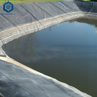
Leachate collection ponds: Liners for leachate storage and treatment basins.
Landfill gas collection systems: Liners for condensate collection and containment.
A major project in the United Kingdom used 2.0 mm HDPE liners from a leading waste management liner system factory for a 25 ha MSW landfill cell, achieving 30+ years of containment with zero groundwater contamination detected.
Common Industry Problems and Engineering Solutions
Even high-quality liners can encounter issues if design or installation falls short. Below are four recurring problems and their engineering remedies for waste management liner systems.
Problem 1: Stress cracking near leachate collection pipes
Root cause: Differential settlement and chemical attack at stress points.
Solution: Use prefabricated boots with expansion loops; specify NCTL ≥500 h; conduct post-installation leak detection surveys.
Problem 2: Puncture from sharp waste particles
Root cause: Inadequate protective layer or insufficient liner thickness.
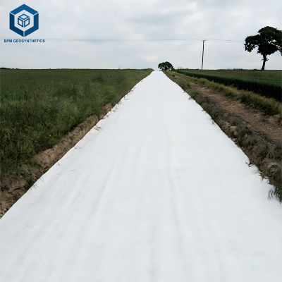
Solution: Install 500 g/m² nonwoven geotextile as cushion; specify thickness ≥2.0 mm for high-load areas.
Problem 3: Seam failure due to improper welding
Root cause: Contamination or incorrect weld temperature under field conditions.
Solution: Perform peel and shear tests on test strips before each shift; use dual-track extrusion welders with automatic temperature control.
Problem 4: UV degradation on exposed side slopes
Root cause: Insufficient carbon black content or lack of protective cover.
Solution: Specify ≥2.5% carbon black and apply a spray-on UV coating for exposed areas.
Risk Factors and Prevention Strategies
Engineering risk management for projects involving a waste management liner system factory includes five critical areas:
Improper liner selection: Choosing inadequate thickness or resin type. Prevention: conduct chemical compatibility testing with site-specific leachate samples.
Material mismatch: Using non-compatible geomembranes for different zones. Prevention: ensure all liner materials come from the same production lot and are chemically compatible.
Environmental exposure: High UV and thermal cycling. Prevention: use high-carbon-black content and cover exposed areas promptly.
Subgrade issues: Sharp rocks or differential settlement. Prevention: perform subgrade proof-rolling; install geotextile cushion layers.
Quality control gaps: Insufficient seam testing. Prevention: implement 100% seam testing (vacuum/air pressure) and independent third-party CQA.
Procurement Guide: How to Choose the Right Waste Management Liner System Factory
Buyers should follow this step‑by‑step checklist when engaging a waste management liner system factory:
Traffic load evaluation – Assess waste loading and equipment traffic to specify puncture resistance and thickness.
Specification verification – Confirm thickness, stress-crack resistance (NCTL), and chemical resistance data against project design criteria.
Certifications – Require ISO 9001, GRI-GM13, and ASTM compliance; request chemical immersion test reports for site-specific leachate.
Factory capability – Audit factory capacity, lead times, and track record on similar waste management projects.
Quality control – Review in-house testing frequency, NCTL measurements, and third-party lab reports.
Sample testing – Request 1 m² samples for independent chemical immersion, puncture, and tensile tests.
Warranty evaluation – Examine warranty covering material defects, seam integrity, and stress-crack performance (≥10 years).
Engineering Case Study
Project: 25 ha MSW landfill cell expansion
Location: Southeast England
Size: 500 m × 500 m cell, 20 m waste height, 2.5H:1V side slopes
Product specification: 2.0 mm textured HDPE liner from a certified waste management liner system factory with NCTL ≥600 h, 2.5% carbon black, and chemical resistance verified in pH 4.5–9.5 leachate; 500 g/m² geotextile underlay; double-welded seams with 100% air pressure testing.
Results & benefits: Installation completed in 50 days with zero leaks detected during hydrostatic testing. After 5 years of operation, groundwater monitoring showed no leachate migration. The liner system exceeded UK Environment Agency requirements and saved the project £2M in potential remediation and compliance costs.
FAQ Section
Typically 1.5–2.5 mm (60–100 mil), with 2.0 mm being the most common for MSW applications.
Notched Constant Tensile Load (ASTM D5397) measures stress-crack resistance; ≥500 hours is critical for leachate environments.
Yes — but chemical immersion testing (ASTM D5322) should be performed for site-specific leachate composition.
25–50 years with proper material selection and installation.
Textured liner provides higher friction (interface angle >25°) and is preferred for slopes steeper than 3H:1V.
ISO 9001, GRI-GM13, and ASTM compliance; additionally, chemical resistance data for site-specific leachate.
Using vacuum box (ASTM D6392) or air pressure testing (ASTM D7406) for 100% seam coverage.
Yes — but they require enhanced UV stabilizers (≥2.5% carbon black) and regular inspections.
HDPE offers higher stress-crack resistance and chemical stability; LLDPE is more flexible but less chemically resistant.
Most reputable factories offer CQA (Construction Quality Assurance) guidance and weld training.
Request Technical Support or Quotation
For project-specific engineering assistance, product samples, or detailed technical datasheets from a qualified waste management liner system factory, our technical advisory team is available. We provide:
Customized liner selection based on waste type, leachate chemistry, and site conditions
Free 1 m² sample panels for independent chemical and mechanical testing
Full technical specifications and installation CQA guidelines
Direct consultation with polymer and environmental engineers
Submit your project parameters through the contact form on our website to receive a detailed engineering proposal within 48 hours.
About the Author
This guide was prepared by senior industry engineers with over 15 years of experience in geomembrane manufacturing, waste management infrastructure, and environmental containment across Europe, North America, and Asia. Our team has contributed to EPC projects for MSW landfills, leachate ponds, and gas collection systems, providing technical due diligence, factory audits, and post-installation performance monitoring. We are not affiliated with any specific brand or platform — our advice is independent and rooted in engineering principles and field failure analysis.