Smooth vs Textured HDPE Geomembrane: Slope Stability Design Guide
What is Smooth vs Textured HDPE Geomembrane Slope Stability Difference
When designing lined slopes for landfills, ponds, reservoirs and containment facilities, the most important material decision is whether to specify a smooth HDPE geomembrane or a textured geomembrane. The short answer: textured HDPE geomembrane delivers an interface friction angle of 25–35°, while smooth HDPE geomembrane typically reaches only 18–22° on compacted clay or GCL. That 8–12° difference raises the factor of safety against downslope sliding by roughly 30–50% and is the decisive factor for any slope steeper than 1V:3H.
This guide explains the physical mechanism behind the friction gap, compares test data from ASTM D5321 interface shear testing, walks through real landfill and pond liner failures,and gives procurement managers a step-by-step specification checklist. Every figure below comes from standard test methods (ASTM D5321, D7466, D6392), GRI-GM13, EPA Subtitle D guidance, and documented project records.
1. Why Surface Texture Controls Slope Stability
The performance difference between smooth and textured HDPE geomembrane is governed by surface asperity height (texture depth). On a 1.5mm HDPE geomembrane, the smooth face has an effectively flat surface below 0.05 mm roughness, while the textured face carries raised pyramids, nodules or sand-like features of 0.25–0.75 mm (typically 0.5 mm).
The mechanism is mechanical interlocking, not adhesion. Texture asperities penetrate the adjacent compacted clay, GCL bentonite or protection geotextile and create a composite shear zone. The engineering consequences are measurable:
Friction against compacted clay (PI ≥ 15, 95% Proctor): smooth 18–22°, textured 25–32°.
Friction against hydrated needle-punched GCL: smooth 16–20°, textured 23–30° — GCL is lower for both because bentonite lubricates the interface.
Friction against non-woven geotextile (300–500 g/m²): smooth 14–18°, textured 22–28°.
Peak vs residual strength: smooth drops from 20° peak to 14° residual (30% loss) after sliding; textured drops from 28° to 24° (only 15% loss), so it holds up better under seismic and creep loading.
The practical result is steeper allowable slopes. Smooth geomembrane becomes marginal at 1V:3H (18.4°) and fails beyond it, while textured geomembrane remains stable up to roughly 1V:1.5H (33.7°), letting designers cut earthwork volume by 20–40%.
2. How Manufacturing Creates Smooth and Textured Surfaces
The surface difference starts on the extrusion line, and it affects both the friction and the welding behavior of the finished liner.
Smooth HDPE geomembrane is extruded through a flat die onto a polished chrome chill roll, producing a glossy, uniform face with roughness under 1 μm. Quality control focuses on thickness uniformity (±5%) and pinhole detection (25 kV spark test), plus off-line tensile, puncture, OIT and carbon black testing per batch.
Textured HDPE geomembrane is made by one of two methods:
Nitrogen gas injection — gas bubbles are injected into the molten polymer just before the die; bubbles expand and rupture at the surface into a sandpaper-like texture. Chill roll temperature controls texture depth. This method produces single-sided or double-sided texture.
Embossed roll — the sheet passes between patterned rolls that imprint pyramids, nodules or grooves. This gives more uniform geometry but can create stress concentrations at pattern corners.
Texture is verified with a laser profilometer or stylus per ASTM D7466. Minimum asperity height is 0.25 mm for single-sided and 0.4 mm for double-sided texture; rolls below 0.2 mm or with bald spots are rejected. Textured rolls need spacers during storage and shipping so the asperities are not flattened.
3. Smooth vs Textured Performance Side by Side
Comparing the two across the metrics that matter most for slope design:
| Performance factor | Smooth HDPE | Textured HDPE | Slope winner |
|---|---|---|---|
| Peak friction, clay | 18–22° | 25–32° | Textured |
| Static FS, 1V:2.5H (21.8°) | 0.9–1.1 (FAIL) | 1.4–1.8 (PASS) | Textured |
| Residual friction post-slip | 14–16° | 23–26° | Textured |
| Max slope at FS=1.5 | 1V:3H (marginal) | 1V:1.9H (stable) | Textured |
| Single-sided available | No | Yes | Textured |
| Cost per m² (1.5 mm) | $5.00–8.00 | $6.50–10.00 | Smooth (cheaper) |
| Yield tensile reduction | Baseline | 5–10% lower | Smooth |
| Puncture resistance | 300 N baseline | Similar | Tie |
Texturing costs 20–30% more, but the premium is small insurance: for a 10-hectare landfill with 50,000 m² of sloped area, the texture premium is roughly $75,000–100,000, versus $500,000–2,000,000 to remediate a single slope failure. Designers should derate the yield tensile strength of textured sheets by 5–10% when sizing the liner.
4. Where Texture Matters in Real Applications
Landfill side slopes (MSW, hazardous, CCR). HDPE geomembrane for landfill side slopes steeper than 1V:3H should always be textured, with asperity ≥ 0.5 mm and interface friction ≥ 25°, per GRI-GM13 and EPA guidance. Smooth sheets on side slopes have caused numerous failures.
Landfill base liner. For horizontal or slopes under 1V:10H, smooth geomembrane is acceptable because the gravity component normal to the slope is minimal; it also welds more easily and costs less.
Landfill final cover (cap). Textured geomembrane is required on cap slopes (typically 1V:3H to 1V:2H) so the cover soil does not slide and expose the liner to UV. Friction against the overlying geotextile or drainage layer must be at least 22°.
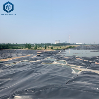
Pond and reservoir liners. For pond side slopes steeper than 1V:4H — irrigation, fire protection, wastewater, potable water and mining process water — textured geomembrane resists slippage from wave action, ice push and filling/draining cycles. Small ponds under 0.5 hectare with gentle slopes can use smooth.
Secondary containment berms. Berm slopes often reach 1V:1.5H to 1V:1H (34–45°), so double-sided textured geomembrane is mandatory; smooth sheets slide immediately under load.
Tunnels and underground containment. Smooth is usually preferred because slopes are not steep and texture could abrade other liners.
5. Real Failures and What They Teach
Case 1 — Landfill side slope slide. A 1V:2.5H (22°) side slope lined with smooth HDPE over GCL slid 1.5 m downslope after waste reached 10 m height, tearing at the anchor trench and releasing leachate. ASTM D5321 showed 17° peak / 13° residual friction against the project GCL, giving a static FS of 0.85. Replacement with textured geomembrane (0.5 mm asperity) raised friction to 26°/23° and FS to 1.65. Remediation cost $2.5 million.
Case 2 — Final cover slide. A cap slope at 1V:2H with smooth HDPE under 600 mm of cover soil slid after the first winter, exposing the liner to UV. The smooth-to-nonwoven-geotextile interface was only 16° peak. Double-sided textured geomembrane raised it to 26° and FS from 0.9 to 1.7.
Case 3 — Seismic loading. A 0.25g earthquake moved a smooth HDPE liner 300 mm on a 1V:3H slope at a hazardous waste landfill, because static FS was 1.2 and seismic inertial forces cut it to 0.6. Retrofitting with textured geomembrane gave 28° static / 25° dynamic friction and a seismic FS of 1.3.
Case 4 — Reversed orientation. A single-sided textured liner was installed with texture facing down. The smooth face toward the cover soil gave only 15° friction, and the soil slid. Marking each roll "TOP" and "BOTTOM" and using double-textured sheets on caps eliminates this class of error.
6. Risk Factors and How to Prevent Them
Relying on published friction values. Always run project-specific ASTM D5321 direct shear testing on the actual material combination (geomembrane-to-clay, to-GCL, to-geotextile) at field normal stresses of 10–200 kPa, and report both peak and residual angles.
Smooth geomembrane over GCL. Bentonite lubricates the interface and can drop friction to 12–15°. Never use smooth over GCL on slopes steeper than 1V:5H; always specify textured with ≥ 0.5 mm asperity.
Moisture at the interface. Water or leachate reduces friction by 2–5° on smooth sheets through pore pressure buildup; textured loses only 1–2°. Keep leachate head under 0.3 m and install a geonet or sand drainage layer on caps.
Soft subgrade. If the underlying clay has undrained shear strength under 25 kPa, the whole liner system can slide on the clay even with textured sheets. Compact or stabilize the subgrade first.
Asperity flattening under deep waste. Under normal stress above 500 kPa, texture can creep and flatten. For waste deeper than 40 m, specify asperity ≥ 0.75 mm and run ASTM D7947 creep testing.
Installation damage. Dragging textured sheets over rough subgrade abrades asperities. Use a 100–150 mm sand cushion or non-woven geotextile protection layer and inspect texture depth after deployment.
7. Procurement Checklist: Smooth or Textured for Your Project
Calculate slope angle and required FS. Minimum 1.5 static and 1.3 seismic. For slopes over 1V:3H, smooth is unlikely to pass — choose textured.
Run ASTM D5321 interface shear testing on production samples at 25, 50, 100 and 200 kPa. Do not rely on literature values.
Compute FS as tan(φ)/tan(θ) for simple slopes, or use limit-equilibrium software (Slide, Slope/W) for complex geometries.
Choose texture type. Single-sided (texture on the waste/cover side) suits most side slopes and caps; double-sided is required for steep slopes over 1V:2H, high seismic zones, or when both interfaces need high friction. Confirm with the 2mm textured HDPE geomembrane and 1mm smooth HDPE geomembrane product data.
Require a test report from an accredited lab (GAI-LAP or equivalent), and reject textured sheets with peak friction under 25° on clay or GCL.
Verify texture uniformity with laser profilometry every 10,000 m²; reject bald spots and depths under 0.2 mm.
Compare cost vs risk. The 20–30% texture premium is minimal insurance against slope-failure remediation.
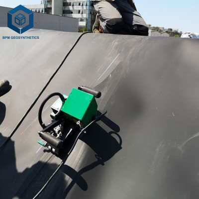
Specify welding. Textured geomembrane usually requires extrusion welding because fusion welders cannot hold consistent pressure on an uneven surface; run welding trials before production. Seam peel ≥ 250 N/50 mm and shear ≥ 350 N/50 mm.
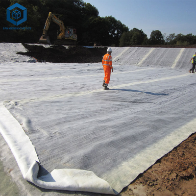
Design the anchor trench for texture. Depth ≥ 0.6 m, width ≥ 0.3 m, backfill with compacted clay, and avoid sharp bends that crack the texture.
Verify after installation. Inspect texture depth at 10 random points per hectare and run an electrical leak location (ELM) survey.
8. Engineering Case Study: Slope Stability Comparison
Project: 10-hectare municipal solid waste landfill cell, side slopes at 1V:2.5H (21.8°), Pacific Northwest, USA (seismic zone 2B, PGA 0.20g), 60,000 m² of side-slope liner.
Alternatives evaluated:
A1 — Smooth HDPE (1.5 mm) using literature friction: φpeak 18° / φres 14° against GCL. Static FS 0.85, seismic FS 0.55 — failed.
A2 — Smooth HDPE (1.5 mm) tested with the project GCL: φpeak 19.2° / φres 15.1°. Static FS 0.92, seismic FS 0.62 — still failed. This confirmed literature values were unreliable.
A3 — Single-sided textured HDPE (asperity 0.55 mm), tested: φpeak 27.8° / φres 24.3°. Static FS 1.68, seismic FS 1.38 — passed.
Selection and results: The owner chose A3 despite the $1.50/m² premium ($90,000 total). After seven years of operation there was no measurable liner movement (< 5 mm at monitoring points), leachate head stayed under 0.1 m, and a 0.18g seismic event at year four caused no displacement. The $90,000 premium avoided a potential $2–3 million failure remediation.
Recommendation: Specify textured geomembrane on all landfill side slopes steeper than 1V:5H regardless of calculated FS — the cost premium is negligible compared to failure risk.
FAQ
1. What is the main difference between smooth and textured HDPE geomembrane for slope stability?
The main difference is interface friction angle. Smooth HDPE geomembrane on clay or GCL has friction angle of 18-22°, while textured geomembrane (asperity ≥0.5 mm) achieves 25-32°. This 8-12° difference increases factor of safety against sliding by 30-50%, allowing steeper slopes (up to 1V:1.9H with textured vs 1V:3H maximum for smooth).
2. For what slope angle is textured geomembrane required?
Textured geomembrane is required for slopes steeper than 1V:3H (18.4°) in most landfill and containment applications. For slopes 1V:3H to 1V:2H (18.4°-26.6°), smooth geomembrane typically fails factor of safety requirements (FS<1.5). textured="" geomembrane="" is="" also="" required="" for="" all="" seismic="" zones="">0.1g peak ground acceleration) regardless of slope angle.
3. How is interface friction angle measured for geomembrane?
ASTM D5321 – Direct shear test. A sample of geomembrane is placed in contact with the interface material (clay, GCL, or geotextile) under a normal stress (e.g., 50, 100, 200 kPa). The sample is sheared horizontally at constant rate (1 mm/min). Shear stress vs displacement is recorded; peak and residual friction angles are calculated. Test must be performed at normal stresses representative of field conditions.
4. Can smooth geomembrane be used on slopes if anchor trenches are provided?
Anchor trenches provide pullout resistance at the slope crest and toe, but they do not prevent sliding on the slope face itself. If the interface friction angle is insufficient, the geomembrane will stretch and potentially rupture between anchor trenches. For slopes >1V:3H, anchor trenches alone are not sufficient – textured geomembrane is required.
5. Does textured geomembrane cost more than smooth?
Yes – textured HDPE geomembrane typically costs 20-30% more than smooth. For 1.5 mm thickness: smooth $5.00-8.00 per m², textured $6.50-10.00 per m². However, the premium is small compared to earthwork savings (steeper slopes reduce excavation volume) and failure remediation cost. The smooth vs textured HDPE geomembrane slope stability difference justifies the premium.
6. How does moisture affect the friction angle of smooth vs textured geomembrane?
Moisture at the interface reduces friction for both types, but smooth is more affected. For smooth geomembrane on clay, saturated interface can reduce friction angle by 3-5° (e.g., from 20° to 16°). For textured geomembrane, reduction is 1-2° because mechanical interlocking remains effective even when wet. Always test at expected moisture conditions.
7. Can I use smooth geomembrane on GCL?
Not recommended on slopes >1V:5H. Smooth geomembrane on GCL typically has friction angle of 16-20° (lower than on clay). For side slopes (>1V:3H), smooth on GCL will almost certainly fail (FS<1.0). Always specify textured geomembrane (asperity ≥0.5 mm) over GCL. Confirm with ASTM D5321 testing.
8. What is the required asperity height for textured geomembrane?
GRI GM13 requires minimum asperity height of 0.25 mm (0.010 inch) for single-sided textured geomembrane. For steep slopes (>1V:2H) or seismic zones, specify asperity ≥0.5 mm (0.020 inch). Measure per ASTM D7466 using laser profilometer. Reject rolls with average asperity<0.2 mm.
9. Does texturing reduce the tensile strength of HDPE geomembrane?
Yes – texturing can reduce tensile strength at yield by 5-10% due to stress concentrations at asperities. For example, smooth 1.5 mm HDPE may have yield strength 27 MPa; textured same thickness may be 24-25 MPa. Design should account for this reduction. However, the slope stability benefit far outweighs the minor tensile reduction.
10. How do I weld textured HDPE geomembrane?
Textured geomembrane requires extrusion welding (not dual-track fusion welding) in most cases because fusion welders cannot achieve consistent pressure on the uneven surface. Extrusion welding uses a extruder gun to apply molten HDPE rod into a prepared V-groove. Welding parameters: 200-240°C, travel speed 0.3-0.6 m/min. Seam testing per ASTM D6392 – peel strength ≥250 N/50mm, shear ≥350 N/50mm. Conduct welding trials before production.
Get Technical Support or a Quotation
If you are evaluating smooth vs textured HDPE geomembrane for your landfill, pond, reservoir or containment project, our engineering team can help. As an HDPE liner manufacturer with 25 years of geosynthetic experience, we provide:
ASTM D5321 interface shear testing (geomembrane-to-clay, to-GCL, to-geotextile) at an accredited lab
Static and seismic factor-of-safety calculations
Laser-profilometry texture depth measurement per ASTM D7466
Sample rolls (2 m²) of smooth and textured HDPE geomembrane for your own testing
A procurement specification template covering texture depth, friction angle and welding requirements
Failure investigation for existing slopes with suspected geomembrane sliding
Contact our senior geosynthetic engineer through the official channels on our website for project-specific guidance and HDPE geomembrane quotations.