How to calculate geomembrane thickness required
Geomembrane thickness calculation refers to the engineering process of determining the required liner thickness based on mechanical loads, subgrade conditions, and chemical exposure. Proper thickness selection ensures structural integrity, puncture resistance, and long-term containment performance in environmental and industrial applications.
Technical Parameters & Specifications
| Parameter | Typical Design Range |
|---|---|
| Thickness | 0.75 mm – 3.0 mm |
| Tensile Strength | ≥ 25 – 30 kN/m |
| Puncture Resistance | ≥ 400 – 800 N |
| Elongation at Break | ≥ 700% |
| Density | ≥ 0.94 g/cm³ (HDPE) |
| Stress Crack Resistance | ≥ 500 hours |
| Hydraulic Conductivity | < 1×10⁻¹³ cm/s |
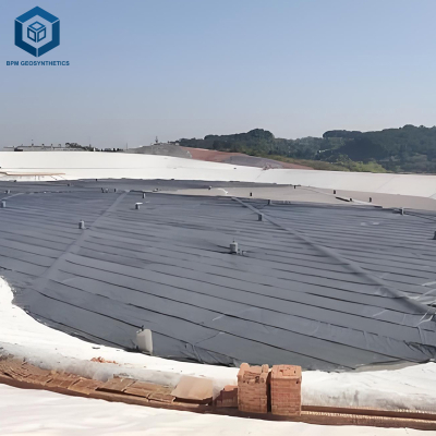
Structure & Material Composition
Geomembrane Layer: HDPE / LLDPE primary barrier
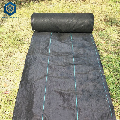
Protection Layer: Nonwoven geotextile (300–800 g/m²)
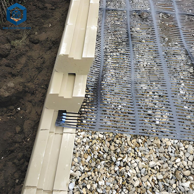
Drainage Layer: Geonet or granular layer
Subgrade: Compacted soil or clay liner
Additives: Carbon black (UV resistance), antioxidants
Manufacturing Process
Raw Material Mixing: Polymer resin with stabilizers.
Extrusion: Flat die or blown film process.
Thickness Calibration: Precision roller system control.
Cooling: Stabilization of material structure.
Surface Treatment: Smooth or textured finish.
Quality Control: Mechanical and permeability testing.
Engineering Calculation Method (Core Section)
1. Puncture Resistance-Based Calculation
Required thickness is often determined by ensuring the geomembrane can resist puncture forces from subgrade and applied loads:
t ≥ √(F / (k × σ))
t = required thickness (mm)
F = applied load (N)
σ = allowable stress (kN/m²)
k = safety factor (typically 2.0–3.0)
2. Empirical Design Method
Light-duty (water ponds): 0.75 – 1.0 mm
Medium-duty (wastewater, reservoirs): 1.0 – 1.5 mm
Heavy-duty (landfills, mining): 1.5 – 2.5 mm
3. Load-Based Design Considerations
Overburden pressure (waste, ore, water)
Subgrade roughness
Traffic load (construction equipment)
Chemical degradation factors
Industry Comparison (Thickness vs Application)
| Application | Recommended Thickness | Risk Level |
|---|---|---|
| Water Reservoir | 0.75 – 1.0 mm | Low |
| Wastewater Pond | 1.0 – 1.5 mm | Medium |
| Landfill | 1.5 – 2.0 mm | High |
| Mining Heap Leach | 2.0 – 3.0 mm | Very High |
Application Scenarios
EPC Contractors: Design of containment systems.
Consulting Engineers: Specification and risk assessment.
Developers: Infrastructure and environmental projects.
Distributors: Supplying geomembranes for various industries.

Core Pain Points & Solutions
Underestimating Required Thickness:
Solution: Perform load-based calculation with safety factor.Puncture Failure Risk:
Solution: Combine thickness selection with geotextile protection.Overdesign Increasing Cost:
Solution: Use optimized thickness based on actual conditions.Ignoring Chemical Impact:
Solution: Adjust thickness and material based on chemical exposure.Subgrade Variability:
Solution: Improve subgrade preparation to reduce required thickness.
Risk Warnings & Mitigation
Insufficient thickness → Leads to puncture and leakage failure.
Ignoring safety factors → Underestimation of design loads.
Poor installation → Reduces effective thickness performance.
Low-quality materials → Inconsistent mechanical properties.
Procurement & Selection Guide
Define application type and risk level.
Calculate expected load and stress conditions.
Apply safety factor (≥2.0).
Select thickness based on calculation and standards.
Verify compliance with GRI GM13 or equivalent.
Request technical datasheets and test reports.
Confirm supplier installation and QA/QC support.
Engineering Case Study
A landfill project required geomembrane thickness calculation based on a 20 m waste load. Engineering analysis recommended 2.0 mm HDPE with geotextile protection. After installation, monitoring over 5 years confirmed no puncture or leakage, validating the calculation-based thickness selection approach.
FAQ (Frequently Asked Questions)
1. How to calculate geomembrane thickness required?
Based on load, puncture resistance, and safety factor.2. What is the standard thickness?
1.5–2.0 mm for most heavy-duty applications.3. Is calculation always necessary?
Yes, for critical engineering projects.4. What is the safety factor?
Typically 2.0–3.0.5. Does subgrade affect thickness?
Yes, rough subgrade increases required thickness.6. Can thinner liner be used with protection?
Sometimes, with geotextile cushioning.7. What is the key failure mode?
Puncture and stress cracking.8. What standards apply?
GRI GM13.9. Is HDPE the best material?
Yes, for most applications.10. What is the main design factor?
Load and environmental conditions.
Call to Action (CTA)
For geomembrane thickness calculation support, engineering design consultation, and product samples, contact our technical team. We provide customized solutions, datasheets, and full project support for global containment applications.
E-E-A-T: Authoritative Expertise
This article is developed by geomembrane engineers with over 10 years of experience in containment system design. Our team has supported landfill, mining, and water infrastructure projects worldwide, providing reliable and optimized thickness calculation solutions.