How to Calculate Geomembrane Quantity for Reservoir Lining Project
For civil engineers, EPC contractors, and procurement managers, knowing how to calculate geomembrane quantity for reservoir lining project is the first step toward accurate budgeting, waste reduction, and successful installation. Underestimating leads to costly emergency orders and splicing; overestimating results in unnecessary material expenses. The calculation process involves mapping the reservoir’s three-dimensional surface area (bottom plus side slopes), accounting for roll overlaps (typically 75–150 mm), anchor trench allowances, and an unavoidable wastage factor (5–10% depending on shape complexity). This guide provides a step-by-step engineering methodology, including formulas for prismoidal and conical shapes, geotextile underlayment estimation, and practical rules for ordering factory-fabricated panels versus field-welded rolls. Procurement managers will learn how to specify quantities in tenders and verify supplied areas against actual needs.
What is How to Calculate Geomembrane Quantity for Reservoir Lining Project
The process of how to calculate geomembrane quantity for reservoir lining project refers to the systematic determination of the total surface area of geomembrane (typically HDPE or LLDPE) required to line a reservoir, including the floor, side slopes, anchor trenches, and allowances for overlaps and waste. Unlike simple geometric area, reservoirs feature sloped banks, curved corners, and transition zones that require precise measurement. The calculation must also consider the standard roll width (typically 5 m to 9 m) and length (50 m to 200 m), as well as the seam layout plan. Overlaps (usually 100 mm for fusion welding) add 2–3% to the net area. Anchor trenches (0.5 m × 0.5 m) add linear meters of liner. Accurate quantity estimation prevents project delays, reduces field splices (which are potential leak points), and optimizes procurement cost. Errors of 10% in a 100,000 m² project translate to $30,000–$50,000 of unnecessary material or reorder costs.
Technical Specifications of How to Calculate Geomembrane Quantity for Reservoir Lining Project
To execute how to calculate geomembrane quantity for reservoir lining project, the following parameters must be known.
| Parameter | Typical Value / Input | Engineering Importance |
|---|---|---|
| Reservoir top area (survey data) | Length (L) x Width (W) at full supply level (FSL) | Base for prismoidal or average area formula. |
| Reservoir bottom area (survey data) | Length (Lb) x Width (Wb) at bottom | Used with top area to compute average area for sloped sides. |
| Side slope angle / ratio | e.g., 1V:3H to 1V:5H (horizontal:vertical) | Increases surface length compared to horizontal projection; slope factor = sqrt(1 + (H/V)²). |
| Reservoir depth (H) | Max water depth (2m to 20m) | Depth times slope factor = slanted length. |
| Roll width (Wr) | 5.0 m to 9.0 m (typical 7 m) | Determines number of longitudinal seams; wider rolls reduce seams. |
| Overlap allowance (fusion welding) | 75 mm – 150 mm (typical 100 mm) | Adds ~2-3% to net area; essential for field seaming. |
| Anchor trench dimensions | Depth 0.5 m, width 0.5 m (typical) | Adds linear meters of liner: perimeter length × (trench perimeter allowance). |
| Wastage factor | 5% – 10% (depending on shape complexity) | Covers cuts for irregularities, curved corners, and installation damage. |
Material Structure and Composition
The how to calculate geomembrane quantity for reservoir lining project is independent of material type, but different geomembranes (HDPE, LLDPE, EPDM) have different roll widths and seam allowances, affecting quantity. The table below shows typical roll dimensions.
| Geomembrane Type | Typical Roll Width (m) | Typical Roll Length (m) | Overlap Requirement (mm) |
|---|---|---|---|
| HDPE (smooth) | 5.0 – 9.0 (common 7.0) | 50 – 200 (common 100) | 100 |
| LLDPE (smooth) | 5.0 – 8.0 | 50 – 150 | 100 |
| EPDM (rubber) | 3.0 – 6.0 | 30 – 60 | 75 (taped) |
| Textured HDPE | 5.0 – 7.0 | 50 – 100 | 150 |
Manufacturing Process and Quantity Estimation
The manufacturing process does not directly affect quantity calculation, but understanding standard panel sizes helps in layout optimization.
Extrusion to width: Flat die extrusion produces rolls of fixed width (e.g., 7 m). The estimator must align reservoir width with roll width to minimize longitudinal seams.
Factory fabrication (optional): For large reservoirs, panels can be factory-welded into custom widths (up to 30 m) to reduce field seams. This reduces overlap allowance but requires custom ordering.
Roll marking: Each roll is labeled with actual length and width. Quantity calculation must use net length, not nominal.
Packaging and shipping: Rolls are palletized. Over-ordering by 5-10% ensures sufficient material even if some rolls are damaged in transit.
Performance Comparison of Quantity Estimation Methods
Different approaches to how to calculate geomembrane quantity for reservoir lining project yield varying accuracy and material efficiency.
| Method | Accuracy (error %) | Time required | Software needed | Best application |
|---|---|---|---|---|
| Manual geometry (prismoidal + slope factor) | ±10-15% (for simple shapes) | 2-4 hours | Calculator, spreadsheets | Small rectangular reservoirs, pre-bid estimates |
| CAD planimeter (2D area + slope factor) | ±5-8% | 1-2 hours | AutoCAD, Civil 3D | Irregular perimeters, moderate complexity |
| 3D surface modeling (DTM / GIS) | ±2-4% | 1 day (modeling) | GIS, Civil 3D, Revit | Complex reservoir shapes, curved slopes, tender-quality quantities |
| Roll layout simulation (nesting) | ±2-3% (plus wastage) | 2 days | Specialized geomembrane nesting software | Large projects (>100,000 m²), optimizing seam placement |
Industrial Applications of Quantity Calculation
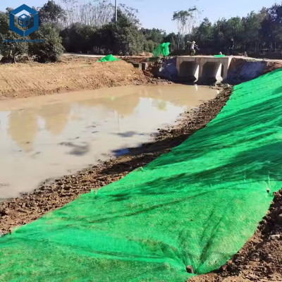
Knowing how to calculate geomembrane quantity for reservoir lining project applies to various water containment structures:
Farm irrigation ponds: Simple rectangular or circular shapes. Manual prismoidal method sufficient. Small quantities (5,000–50,000 m²).
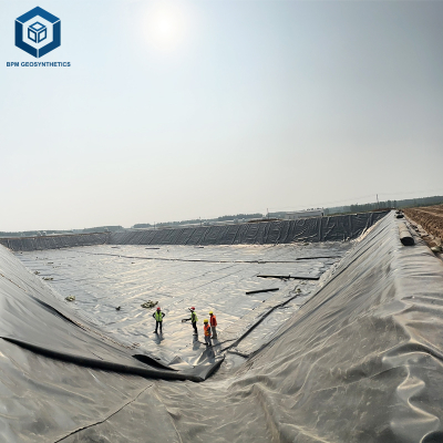
Municipal water reservoirs: Large, often irregular perimeters. Requires 3D survey and CAD modeling. Quantities range 50,000–500,000 m².
Mining tailings evaporation ponds: Multiple cells, complex geometries. Advanced nesting software to minimize seams.
Industrial fire water ponds: Moderate size, often rectangular with 1V:3H slopes. CAD method works.
Aquaculture shrimp/tilapia ponds: Many small ponds. Roll width optimization across multiple cells.
Common Industry Problems and Engineering Solutions
Errors in how to calculate geomembrane quantity for reservoir lining project lead to four common field issues.
Problem: Underestimated side slope area (using horizontal projection instead of slanted length).
Root cause: Forgetting slope factor (sqrt(1 + (H/V)²)). Example: 1V:3H slope, depth 5m → horizontal length 15m, slanted length 15.8m (5% longer). Solution: Always multiply horizontal length by slope factor. For 1V:2H, slanted length = depth × 2.236; for 1V:3H, depth × 3.16.Problem: Not accounting for overlaps, leading to field shortage.
Root cause: Estimated net area but ordered net area. Overlaps (100 mm) add 2-3% area. For 100,000 m² net, order 103,000 m². Solution: Add overlap allowance based on seam layout: (number of seams × seam length × overlap width).Problem: Ignoring anchor trenches.
Root cause: Linear meters of trench require extra liner width (0.5m depth + 0.5m width + 0.3m backfill allowance). For perimeter 1000m, add ~1000 m² (0.5m+0.5m width × length). Solution: Calculate trench area as (perimeter length) × (trench allowance width – typically 0.8-1.0 m).Problem: Excessive waste due to roll width mismatch.
Root cause: Reservoir width is not multiple of roll width, causing cut-offs. Example: Reservoir width 35m, roll width 7m → 5 rolls exactly (no waste). Width 36m → need 5 rolls + 1m strip (14% waste). Solution: Optimize roll width selection during design; request custom roll widths from supplier if large project.
Risk Factors and Prevention Strategies
Accurate how to calculate geomembrane quantity for reservoir lining project reduces these risks:
Survey inaccuracy: Prevention: Use high-resolution topographical survey (grid spacing 5m-10m). For existing reservoirs, use sonar bathymetry. Validate with on-site physical measurements.
Material mismatch (roll dimensions vs calculation): Prevention: Confirm actual roll width (not nominal) with supplier before ordering. Some factories provide 6.9m instead of 7.0m. Adjust quantity accordingly.
Environmental changes (erosion of side slopes before lining): Prevention: Re-survey slope after excavation but before geomembrane ordering. Add 5% contingency for slope re-profiling.
Installation damage waste: Prevention: Order 5-10% additional material (wastage factor). For textured or slippery liners, add 10-12% due to handling difficulty.
Procurement Guide: How to Choose the Right Quantity Calculation
For procurement managers, follow this checklist when applying how to calculate geomembrane quantity for reservoir lining project:
Obtain accurate survey data: Digital terrain model (DTM) with contour lines. Extract top and bottom perimeters, depth, slope angles.
Calculate net surface area: Bottom area + (side slope area = (average perimeter × slanted length)). For rectangular reservoirs: total net area = (Lb × Wb) + 2 × (depth × slope factor × (Lb + Wb)). For circular: net = bottom area + (π × D_avg × slanted length).
Add overlap allowance: Determine seam layout (longitudinal and transversal). Estimate total seam length, multiply by overlap width (0.1 m for fusion). Add 2-3% to net area.
Add anchor trench area: Perimeter length × (trench width allowance – typically 1.0 m). Example: perimeter 500 m, trench allowance 1 m → add 500 m².
Add wastage factor: 5% for simple rectangles, 7% for irregular, 10% for complex curved shapes.
Convert to roll quantity: Divide total adjusted area by roll area (width × length). Round up to full rolls. For large projects, request factory-fabricated panels to reduce field seams.
Verify with supplier: Send calculation for review. Some suppliers provide free quantity take-off service. Compare their result to yours.
Engineering Case Study
Project type: Municipal water storage reservoir.
Location: Midwest, USA.
Project size: Top dimensions 240m × 180m, bottom 200m × 140m, depth 6m, side slope 1V:3H.
Calculation steps for geomembrane quantity:
- Bottom area = 200 × 140 = 28,000 m²
- Side slope area: average perimeter = (200+140)×2 = 680 m; slanted length = depth × slope factor = 6 × 3.162 = 18.97 m → side slope area = 680 × 18.97 = 12,899 m²
- Net area = 28,000 + 12,899 = 40,899 m²
- Overlap allowance (3%): +1,227 m² → sub-total 42,126 m²
- Anchor trench: perimeter top = (240+180)×2 = 840 m, trench allowance 1.0 m → +840 m² → sub-total 42,966 m²
- Wastage factor (7% for moderate shape): +3,007 m² → total order quantity = 45,973 m² ≈ 46,000 m²
- Roll selection: roll width 7m, length 100m → area/roll = 700 m² → rolls needed = 46,000 / 700 = 65.7 → order 66 rolls (46,200 m²).
Results: Actual installed area was 45,800 m². Over-order of 400 m² (0.9%) was acceptable as spare for future repairs. No emergency orders needed. Total project cost for geomembrane: $322,000. Estimated savings from accurate calculation (avoiding 15% over-order): $48,000.
FAQ Section
Q: What is the formula for calculating geomembrane area for a rectangular reservoir?
A: Net area = (Lb × Wb) + 2 × D × SF × (Lb + Wb), where D = depth, SF = slope factor = sqrt(1 + (horizontal/vertical)²).Q: How much overlap is required between geomembrane rolls?
A: For HDPE extrusion welding, 100 mm (75-150 mm). For LLDPE and EPDM taped seams, 75 mm. Add 2-3% to net area.Q: Should I include anchor trenches in quantity calculation?
A> Yes. Anchor trenches add significant area. Typically, perimeter length × 1.0 m (0.5m depth + 0.5m width).Q: What wastage factor should I use?
A: 5% for simple rectangular, 7% for moderate irregular, 10% for complex curved shapes, and 12% for textured liners on steep slopes.Q: How to calculate quantity for a circular reservoir?
A: Net = (π × R_bottom²) + (π × (R_top + R_bottom) × slanted height). Slanted height = depth × slope factor.Q: Does software help in quantity calculation?
A: Yes. AutoCAD Civil 3D, GIS (ArcGIS), and specialized geosynthetic design software (e.g., GeoCalc) increase accuracy and speed.Q: How do I convert net area to number of rolls?
A: Divide total adjusted area (net + overlaps + trench + waste) by roll area (width × length). Round up to the nearest whole roll.Q: What if the reservoir has an irregular perimeter?
A: Use planimeter tool in CAD to measure top and bottom perimeters and areas. Then apply average area or prismoidal formula with slope factor.Q: Can I reduce waste by ordering custom panel widths?
A: Yes, many suppliers offer factory-fabricated panels up to 30 m width. This reduces field seams and overlap waste but increases factory cost. Economical for projects >50,000 m².Q: Should I order spare rolls for future repairs?
A: Yes, order 2-3 extra rolls (or 2% of quantity) to keep as repair stock. Store them in a cool, dark warehouse.
Request Technical Support or Quotation
For civil engineers and EPC contractors, technical support is available to review your reservoir survey data, perform quantity take-off, and optimize roll layout. Request a quotation for HDPE/LLDPE geomembrane with factory-fabricated panel options and seam layout drawings.
About the Author
This guide was authored by geosynthetic engineers and civil estimators with over 15 years of experience in water reservoir design, quantity surveying, and construction of lined reservoirs for municipal, agricultural, and mining applications across five continents. All recommendations follow industry standards and best practices for geomembrane installation.