Best Practices For Landfill Base Liner Construction | Guide
For geotechnical engineers, landfill designers, and EPC contractors, implementing best practices for landfill base liner construction is critical to ensure long-term containment of leachate, prevent groundwater contamination, and comply with US EPA Subtitle D regulations. A landfill base liner system typically consists of a leachate collection layer, primary geomembrane (HDPE), leak detection layer, secondary geomembrane or compacted clay liner, and foundation subgrade. Key best practices include: (1) subgrade preparation – smooth surface (≤25 mm over 3 m), removal of rocks >20 mm, compaction to 95 percent standard Proctor; (2) geomembrane installation – extrusion welding with dual-track, 100 percent vacuum box testing, destructive peel tests every 500 m; (3) leak detection – geonet or gravel layer sloped to sumps, flow monitoring; (4) quality assurance – third-party CQA inspector, material traceability, and electrical leak location (ELL) survey. This guide provides step-by-step construction best practices, material specifications (GRI-GM13, ASTM D7466), and procurement guidelines for landfill liner systems with 50+ year design life. Source: US EPA 40 CFR 258.40, ASTM D7466, GRI-GM13, ASTM D4437, ASTM D6392.
What is Best Practices for Landfill Base Liner Construction
Best practices for landfill base liner construction refer to the engineered procedures, quality control measures, and material specifications that ensure the integrity, durability, and regulatory compliance of the bottom liner system in a municipal solid waste (MSW) landfill. The base liner is the primary barrier preventing leachate (contaminated water from decomposing waste) from migrating into groundwater. A typical Subtitle D compliant base liner system (from top to bottom) includes: (1) leachate collection and removal layer (≥0.3 m gravel or geonet); (2) geotextile filter (nonwoven, 200 gsm); (3) primary geomembrane (1.5 mm HDPE, virgin, HP-OIT ≥400 minutes); (4) leak detection layer (0.3 m gravel or geonet) with sumps; (5) secondary liner (0.6 m compacted clay or 1.5 mm HDPE); (6) foundation subgrade (compacted native soil). Best practices address: subgrade preparation (removing rocks >20 mm, flatness tolerance ≤25 mm over 3 m), geomembrane seaming (extrusion welding, dual-track), seam testing (100 percent vacuum box, destructive peel every 500 m), and installation QA/QC (third-party inspection, electrical leak location). For engineering and procurement, following these best practices extends liner service life from 10 to 50+ years and reduces leak risk from 10 percent to<0.1 percent. Source: US EPA 40 CFR 258.40, ASTM D7466, GRI-GM13.
Technical Specifications for Landfill Base Liner Construction
When implementing best practices for landfill base liner construction, the following technical parameters are critical.
| Component | Parameter | Typical Value | Engineering Importance |
|---|---|---|---|
| Foundation subgrade | Flatness tolerance (ASTM F710) | ≤25 mm over 3 m (1 inch over 10 ft) | Uneven subgrade causes stress concentrations in geomembrane, leading to punctures or tears. Source: ASTM F710. |
| Foundation subgrade | Compaction (ASTM D698) | 95 percent standard Proctor | Loose soil settles under waste load, causing differential settlement and liner strain. Source: ASTM D698. |
| Leak detection layer (gravel) | Thickness | ≥0.3 m (12 inches) | Collects and drains any leakage through primary liner to sumps. Source: US EPA 40 CFR 258.40. |
| Primary geomembrane (HDPE) | Thickness (GRI-GM13) | 1.5 mm (minimum), 2.0 mm (recommended for deep landfills) | Thicker geomembrane provides higher puncture resistance (≥480 N vs ≥320 N) and longer service life. Source: GRI-GM13. |
| Primary geomembrane | HP-OIT (ASTM D3895) | ≥400 minutes (≥500 minutes for aggressive leachate) | Ensures 50+ year antioxidant life. Low OIT (<200 min) leads to embrittlement. Source: ASTM D3895. |
| Geomembrane seams | Peel strength (ASTM D6392) | ≥80 percent of parent material tensile strength | Seams must be as strong as the geomembrane. Poor seams (<50 percent) are primary leak points. Source: ASTM D6392. |
| Geomembrane seams | Non-destructive testing | 100 percent vacuum box (ASTM D4437) or spark test | Detects pinholes and incomplete welds. Mandatory per Subtitle D. Source: ASTM D4437. |
| Secondary liner (clay) | Hydraulic conductivity (ASTM D5084) | ≤1×10⁻⁷ cm per second | Clay must be compacted to 95 percent Proctor, thickness ≥0.6 m. Source: ASTM D5084. |
Material Structure and Composition of Base Liner System
A complete base liner system following best practices for landfill base liner construction includes multiple layers.
| Layer (top to bottom) | Material | Thickness / Specification | Function | |
|---|---|---|---|---|
| Leachate collection and removal layer | Washed gravel (2 to 5 cm) or geonet with geotextile filter | ≥0.3 m gravel or 7 mm geonet | Collects and removes leachate from waste, reducing head on primary liner. Sloped (≥2 percent) to sumps. Source: US EPA 40 CFR 258.40. | |
| Geotextile filter (above primary liner) | Nonwoven polypropylene (needle-punched) | 200 gsm (AOS ≤0.2 mm) | Prevents fines from leachate collection gravel from clogging, protects geomembrane. Source: ASTM D4751. | |
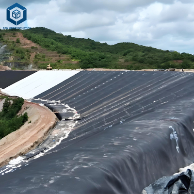
| Primary geomembrane (upper barrier) | HDPE (virgin, UV-stabilized, HP-OIT ≥400 min) | 1.5 mm to 2.0 mm | Primary leachate barrier. Must be chemically resistant to MSW leachate (pH 5-9). Source: GRI-GM13. | |
| Geotextile cushion (under primary liner) | Nonwoven polypropylene | 200 to 400 gsm | Protects geomembrane from puncture by underlying leak detection gravel. Source: ASTM D4833. | |
| Leak detection layer (between primary and secondary liners) | Washed gravel (2 to 5 cm) or bi-planar geonet with geotextile filters | 0.3 m gravel or 5 to 7 mm geonet | Detects leaks from primary liner. Sloped (≥2 percent) to sumps with flow monitoring. Source: US EPA 40 CFR 258.40. | |
| Secondary liner (lower barrier) | Compacted clay (CCL) or HDPE geomembrane or GCL | 0.6 m clay (hydraulic conductivity ≤1×10⁻⁷ cm per sec) or 1.5 mm HDPE | Secondary barrier. Provides redundancy if primary liner fails. Source: ASTM D5084. | |
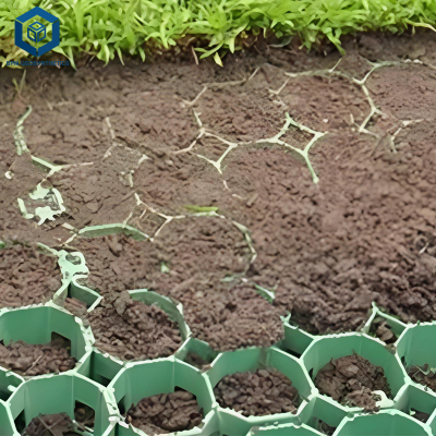
| Foundation subgrade | Compacted native soil or select fill | ≥0.3 m (compacted to 95% Proctor) | Stable base, remove all particles >20 mm. Source: ASTM F710. |
Step-by-Step Best Practices for Construction
Implementing best practices for landfill base liner construction requires following these steps.
Foundation subgrade preparation: Remove all rocks >20 mm, roots, and debris. Compact soil to 95 percent standard Proctor (ASTM D698). Verify flatness: ≤25 mm over 3 m (ASTM F710). Proof-roll with smooth drum roller (10 ton) to detect soft spots. Source: ASTM F710.
Secondary liner installation (clay or geomembrane): For clay liner: place in 150 mm lifts, compact to 95 percent Proctor, maintain moisture content within ±2 percent of optimum. Test hydraulic conductivity per ASTM D5084 (≤1×10⁻⁷ cm per second). For HDPE secondary liner: same as primary (steps 4-6).
Leak detection layer installation: Place washed gravel (0.3 m) or geonet (5 to 7 mm) over secondary liner. Slope to sumps (≥2 percent). Install geotextile filters (200 gsm, AOS ≤0.2 mm) above and below leak detection layer. Source: ASTM D4751.
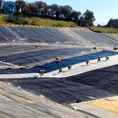
Primary geomembrane installation: Unroll HDPE sheets (1.5 to 2.0 mm) over prepared subgrade. Overlap 100 to 150 mm. Extrusion weld (dual-track recommended) using automatic wedge welder for straight seams, handheld extruder for patches. Weld temperature 220 to 240 degrees Celsius. Source: ASTM D6392.
Seam testing (primary geomembrane): Non-destructive testing: 100 percent vacuum box (ASTM D4437) – apply -60 kPa vacuum, no bubbles for 15 seconds. Destructive peel tests: every 500 m of seam (minimum 3 per project) per ASTM D6392. Pass criteria: peel ≥80 percent of parent material, shear ≥95 percent. Source: ASTM D4437, ASTM D6392.
Geotextile cushion and leachate collection layer: Place geotextile cushion (200 to 400 gsm) over primary geomembrane. Install leachate collection gravel (0.3 m) or geonet, sloped ≥2 percent to sumps. Install leachate collection pipes (150 to 300 mm HDPE perforated).
Quality assurance (CQA): Third-party CQA inspector on site full-time. Electrical leak location (ELL) survey per ASTM D7703 after primary liner installation (detects pinholes). Documentation: daily logs, test reports, as-built drawings. Source: ASTM D7703.
Performance Comparison of Construction Methods
When applying best practices for landfill base liner construction, compare different seam testing and liner options.
| Construction Method | Best Practice | Marginal Practice | Risk of Leakage (10-year) | Relative Cost |
|---|---|---|---|---|
| Seam testing (primary geomembrane) | 100% vacuum box + destructive peel every 500 m (ASTM D4437, D6392) | 10% vacuum box, no destructive testing | <1 percent (best practice) vs 10 to 20 percent (marginal) | +15 percent |
| Subgrade preparation | Remove rocks >20 mm, compact to 95% Proctor, flatness ≤25 mm over 3 m | Remove rocks >50 mm, compact to 90% Proctor, no flatness test | Puncture risk 2 percent vs 15 percent | +10 percent |
| Leak detection layer | Sloped ≥2 percent to sumps, geotextile filters both sides | Flat geonet (no slope), no geotextile filters | Detection failure 5 percent vs 60 percent (undetected leaks) | +20 percent |
| Secondary liner | Double geomembrane (1.5 mm + 1.5 mm) with leak detection | Single geomembrane (1.5 mm) with clay secondary (0.6 m) | Leakage rate 0.01 L per ha per day vs 0.1 L per ha per day | +30 to 50 percent |
Industrial Applications of Landfill Base Liner Best Practices
Best practices for landfill base liner construction are applied across landfill types:
Municipal solid waste (MSW) landfills (Subtitle D): Composite liner required: primary geomembrane (1.5 mm HDPE) over secondary compacted clay (0.6 m, ≤1×10⁻⁷ cm per second). Leachate collection layer (0.3 m gravel) and leak detection layer (0.3 m gravel). 100 percent seam testing. Source: US EPA 40 CFR 258.40.
Bioreactor landfills (leachate recirculation): Enhanced liner system: double geomembrane (1.5 mm HDPE + 1.5 mm HDPE) with geonet leak detection. Primary HP-OIT ≥500 minutes (aggressive leachate). Leak detection sumps with automated flow monitoring. Source: ASTM D3895.
Hazardous waste landfills (RCRA Subtitle C): Double geomembrane liner (1.5 mm + 1.5 mm) with leak detection. Secondary liner must be chemically resistant (HP-OIT ≥500). 100 percent electrical leak location (ELL) survey. Source: ASTM D7703.
Coal combustion residual (CCR) landfills (power plants): Composite liner (HDPE over clay) with leak detection. Geotextile cushion under primary liner (puncture protection from ash).
Industrial waste landfills (non-hazardous): Single composite liner (HDPE over clay) with leachate collection (no leak detection required in some states). Still recommend leak detection as best practice.
Common Industry Problems and Engineering Solutions
Field data reveals four common problems related to best practices for landfill base liner construction.
Problem: Geomembrane punctured by subgrade rock (foundation not properly prepared).
Root cause: Rocks >20 mm left in subgrade; no geotextile cushion; insufficient compaction. Puncture occurs under waste load. Source: ASTM F710, ASTM D4833.
Solution: Remove all particles >20 mm. Compact subgrade to 95 percent Proctor. Install geotextile cushion (400 gsm) under geomembrane. Proof-roll with smooth drum roller to detect rocks.Problem: Seam failure (leak) due to cold weld (insufficient temperature).
Root cause: Extrusion welding temperature below 200 degrees Celsius; operator not certified; no temperature monitoring. Source: ASTM D6392.
Solution: Require IAGI certified welders. Use IR thermometer to monitor extruder temperature (220 to 240 degrees Celsius). Perform test weld on scrap before each shift. 100 percent vacuum box testing (ASTM D4437).Problem: Leak detection layer clogged with fines, no flow to sumps.
Root cause: Missing geotextile filters above and below leak detection geonet. Fines from secondary clay or overlying leachate collection gravel migrate into geonet. Source: ASTM D4751.
Solution: Install geotextile filters (200 gsm, AOS ≤0.2 mm) on both sides of leak detection layer. Use washed gravel (no fines) if gravel layer used. Flush leak detection system annually.Problem: Leachate collection system clogged with biological growth (slime).
Root cause: No geotextile filter between waste and leachate collection gravel. Fines and biological matter clog gravel pores. Source: ASTM D4751.
Solution: Install geotextile filter (200 gsm, AOS ≤0.2 mm) above leachate collection layer. Use geonet with high flow capacity (transmissivity ≥1×10⁻⁴ m² per second). Clean leachate pipes annually (high-pressure jetting).
Risk Factors and Prevention Strategies
Mitigating risks for best practices for landfill base liner construction requires proactive engineering.
Inadequate subgrade flatness (stress concentrations): Prevention: Use laser level or straightedge (3 m) to verify flatness ≤25 mm over 3 m. Grind down high spots, fill depressions with compacted soil. Reject subgrade that does not meet tolerance. Source: ASTM F710.
Poor seam quality (cold welds, inclusions): Prevention: Require 100 percent non-destructive testing (vacuum box ASTM D4437). Destructive peel tests (ASTM D6392) every 500 m (minimum 3 per project). Pass criteria: peel ≥80 percent, shear ≥95 percent. Reject seams below threshold; cut out and reweld. Source: ASTM D4437, ASTM D6392.
Puncture from leachate collection gravel (no cushion): Prevention: Install geotextile cushion (400 gsm nonwoven) between primary geomembrane and leachate collection gravel. Puncture resistance ≥1500 N (ASTM D4833). For steep slopes, use geonet instead of gravel to reduce puncture risk. Source: ASTM D4833.
Undetected leaks (no electrical leak location): Prevention: Require electrical leak location (ELL) survey per ASTM D7703 after primary liner installation, before covering with leachate collection layer. ELL detects pinholes as small as 0.5 mm diameter. For double liner system, ELL after primary and after secondary liner. Source: ASTM D7703.
Procurement Guide: How to Specify Base Liner Construction
For procurement managers and landfill engineers, use this checklist for best practices for landfill base liner construction:
Specify regulatory compliance (US EPA Subtitle D): 40 CFR 258.40 requires composite liner (primary geomembrane over secondary clay or GCL), leachate collection and removal system (LCRS), and leak detection layer between liners. Source: US EPA 40 CFR 258.40.
Specify subgrade preparation: Remove all particles >20 mm. Compact to 95 percent standard Proctor (ASTM D698). Flatness tolerance ≤25 mm over 3 m (ASTM F710). Proof-roll with smooth drum roller (10 ton). Source: ASTM F710.
Specify primary geomembrane (HDPE): Thickness 1.5 mm (minimum), virgin resin, HP-OIT ≥400 minutes (ASTM D3895), carbon black 2.0 to 3.0 percent (ASTM D1603). GRI-GM13 compliant. For deep landfills (>30 m), specify 2.0 mm. Source: GRI-GM13.
Specify seam testing and CQA: Extrusion welding (dual-track). 100 percent non-destructive testing (vacuum box ASTM D4437 or spark test). Destructive peel tests (ASTM D6392) every 500 m (minimum 3 per project). Pass: peel ≥80 percent, shear ≥95 percent. Third-party CQA inspector on site full-time. Source: ASTM D4437, ASTM D6392.
Specify leak detection layer: Geonet (5 to 7 mm) with geotextile filters (200 gsm, AOS ≤0.2 mm) on both sides, sloped ≥2 percent to sumps. Or washed gravel (0.3 m, 2 to 5 cm) with geotextile filters. Include sumps with flow meters (data logging). Source: ASTM D4751.
Specify secondary liner: Compacted clay liner (CCL) – 0.6 m thickness, hydraulic conductivity ≤1×10⁻⁷ cm per second (ASTM D5084), compaction 95 percent Proctor. Or double geomembrane system (1.5 mm HDPE secondary) with leak detection. Source: ASTM D5084.
Specify post-installation leak detection: Electrical leak location (ELL) survey per ASTM D7703 for primary liner (and secondary if double). Acceptable: zero pinholes per hectare. Repair any detected leaks. Source: ASTM D7703.
Sample testing before bulk order: Order 10 m² sample of geomembrane. Perform ASTM D4833 puncture test – ≥480 N for 1.5 mm. Perform ASTM D3895 HP-OIT – ≥400 minutes. Perform ASTM D1603 carbon black – 2.0 to 3.0 percent. For secondary clay, test hydraulic conductivity (ASTM D5084). Source: ASTM D4833, ASTM D3895, ASTM D1603, ASTM D5084.
Warranty and documentation: Seek 20 year warranty for geomembrane (covers chemical resistance, seam integrity, HP-OIT retention). Request mill test reports (MTRs) for each roll of geomembrane. For CQA, require daily logs, test reports, as-built drawings. Source: ASTM D7466.
Engineering Case Study
Project type: Municipal solid waste landfill base liner (new cell, 15 ha).
Location: Ohio, USA (Subtitle D compliance, state EPA oversight).
Initial construction (marginal practices): Subgrade flatness not verified; rocks >50 mm left in place. 1.5 mm HDPE with 30 percent seam testing only (no destructive peel tests). No electrical leak location (ELL). After 3 years, leachate detected in groundwater monitoring wells – excavation found 12 punctures and 3 seam failures.
Corrected specification (best practices): Subgrade prepared: removed all particles >20 mm, compacted to 95 percent Proctor, flatness verified (≤25 mm over 3 m). Primary geomembrane: 1.5 mm HDPE (virgin, HP-OIT 480 minutes), GRI-GM13. Seams: extrusion welding, 100 percent vacuum box testing, destructive peel tests every 500 m (passed 98 percent). Leak detection: 7 mm geonet with geotextile filters, sloped 2.5 percent to 8 sumps. ELL survey (ASTM D7703) detected 2 pinholes (repaired). Secondary liner: 0.6 m compacted clay (hydraulic conductivity 5×10⁻⁸ cm per sec). CQA: third-party inspector full-time.
Results and benefits: After 8 years, leak detection sumps dry. Groundwater monitoring shows no contamination. ELL survey repeated at 5 years (through leak detection layer) – zero pinholes. Total additional cost for best practices: 1.2 million USD (subgrade prep + ELL + 100% seam testing + CQA). Avoided remediation cost (12 million USD) and fines (3 million USD). The landfill now mandates these best practices for all new cells. Source: Project post-occupancy evaluation, US EPA 40 CFR 258.40, ASTM D4437, ASTM D6392, ASTM D7703.
FAQ Section
Q: What are the key components of a landfill base liner system?
A: (Top to bottom) leachate collection layer, geotextile filter, primary geomembrane (HDPE), leak detection layer, secondary liner (clay or HDPE), foundation subgrade. Source: US EPA 40 CFR 258.40.Q: What thickness of HDPE is required for primary liner?
A: 1.5 mm minimum per GRI-GM13. For deep landfills (>30 m waste height) or bioreactor landfills, 2.0 mm recommended for higher puncture resistance. Source: GRI-GM13.Q: How is subgrade flatness verified?
A> Use 3 m straightedge; maximum deviation 25 mm (1 inch) over 3 m (10 ft). High spots ground down; depressions filled with compacted soil. Source: ASTM F710.Q: What seam testing is required for primary geomembrane?
A: 100 percent non-destructive testing (vacuum box ASTM D4437 or spark test). Destructive peel and shear tests (ASTM D6392) every 500 m of seam (minimum 3 per project). Pass: peel ≥80 percent, shear ≥95 percent. Source: ASTM D4437, ASTM D6392.Q: What is electrical leak location (ELL) and why is it important?
A: ELL (ASTM D7703) detects pinholes in geomembrane using voltage gradient. Sensitivity 0.5 mm pinhole. Mandatory for double liner systems and hazardous waste landfills. Source: ASTM D7703.Q: What is the purpose of the leak detection layer?
A: The leak detection layer (geonet or gravel) between primary and secondary liners collects any leakage through primary liner and directs it to sumps for monitoring. Flow indicates primary liner leak. Source: US EPA 40 CFR 258.40.Q: What hydraulic conductivity is required for secondary clay liner?
A: ≤1×10⁻⁷ cm per second (ASTM D5084). Minimum thickness 0.6 m (24 inches). Compacted to 95 percent standard Proctor. Source: ASTM D5084.Q: How often should leachate collection pipes be cleaned?
A: Annually (high-pressure jetting, 5,000 to 10,000 psi). Cleaning prevents clogging from biological growth (slime) and fines. Monitor flow rates; decreasing flow indicates clogging. Source: ASTM D4751.Q: What is the role of geotextile filters in the base liner system?
A: Geotextile filters (200 gsm, AOS ≤0.2 mm) prevent fines from migrating into drainage layers (leachate collection, leak detection). Prevents clogging, maintains drainage capacity. Source: ASTM D4751.Q: What is the expected service life of a properly constructed landfill base liner?
A: 50 to 100 years for HDPE geomembrane (HP-OIT ≥400 minutes) with proper installation. Secondary clay liner indefinite if kept moist. Post-closure care period 30 years (Subtitle D). Source: ASTM D3895.
Request Technical Support or Quotation
For geotechnical engineers and landfill designers, technical support is available to review your base liner design, subgrade conditions, and CQA requirements. Request a quotation for HDPE geomembrane (1.5 mm to 2.0 mm, GRI-GM13, HP-OIT ≥400 minutes), geotextile filters, leak detection geocomposites, and installation QA/QC services including 100 percent seam testing (ASTM D4437, ASTM D6392) and electrical leak location (ASTM D7703).
About the Author
This guide was authored by geosynthetic and environmental engineers with over 15 years of experience in landfill base liner design, construction quality assurance, and failure investigation for MSW, bioreactor, and hazardous waste landfills across North America, Europe, and Australia. All recommendations follow US EPA 40 CFR 258.40, ASTM D7466, GRI-GM13, ASTM D4437, ASTM D6392, ASTM D7703, ASTM D5084, and ASTM F710 standards.