How to Install HDPE Geomembrane Step by Step Guide | Engineer Manual
For CQA engineers, installation contractors, and project managers, a thorough how to install hdpe geomembrane step by step guide is essential for achieving leak-proof containment in landfills, mining heaps, and ponds. After supervising more than 500 geomembrane installations covering 15 million square meters globally, we have developed this definitive how to install hdpe geomembrane step by step guide covering each critical phase: subgrade acceptance (smooth, compacted, free of sharp objects), panel deployment (unrolling, tensioning, anchoring), dual-track fusion welding (temperature 400-500°C, speed 1.5-3.0 m/min), non-destructive testing (air channel at 30 psi), destructive sampling (ASTM D6392 peel/shear), and repair procedures. This engineering manual includes safety protocols, equipment checklists, quality control hold points, and troubleshooting tables for common weld defects. For procurement managers, we include a contractor qualification checklist and inspection schedule.
What is How to Install HDPE Geomembrane Step by Step Guide
The phrase how to install hdpe geomembrane step by step guide refers to the systematic sequence of procedures for deploying, seaming, testing, and commissioning high-density polyethylene liners in containment applications. Industry context: Installation follows ASTM D7003 (thickness), D4437 (non-destructive testing), D6392 (destructive seam testing), and GRI GM13/GM17 specifications. Key phases include: (1) subgrade preparation and acceptance, (2) panel layout and deployment, (3) seaming (fusion welding for primary seams, extrusion welding for repairs), (4) non-destructive testing (air channel, vacuum box), (5) destructive testing (peel and shear), (6) repair of defects, and (7) final protection layer placement. Why it matters for engineering and procurement: Proper installation prevents seam failures (80 percent of leaks) and ensures regulatory compliance (EPA Subtitle D). This guide provides step-by-step instructions with acceptance criteria for each phase.
Technical Specifications – HDPE Geomembrane Installation Parameters
| Parameter | Typical Value / Requirement | Acceptance Criteria | Engineering Importance | |
|---|---|---|---|---|
| Subgrade flatness | ≤3mm over 3m (ASTM F710) | Maximum 3mm deviation | Prevents punctures and ensures uniform support | |
| Subgrade stone size | Maximum 20mm diameter | No sharp objects or angular stones >20mm | Large stones puncture geomembrane under load | |
| Panel overlap (smooth HDPE) | 75-100mm | Minimum 75mm overlap | Insufficient overlap causes machine run-off | |
| Fusion welder temperature | 400°C – 500°C (adjust by thickness) | ±10°C of set point | Too cold = cold weld; too hot = burn-through | |
| Welding speed (dual-track) | 1.5 – 3.0 m/min | Adjust inversely with temperature | Speed affects heat input; critical for consistent bond | |
| Air channel test pressure | 30 psi (2 bar) | Hold 5 minutes, decay ≤20% | Detects leaks in dual-track seams | |
| Peel test acceptance | ≥31 N/cm or 50% of parent sheet .=Minimum bond strength for primary seams |
Material Structure and Composition – Installation Considerations
| Layer / Component | Material | Installation Consideration | Quality Check |
|---|---|---|---|
| HDPE core | HDPE resin + carbon black + antioxidants | Protect from UV exposure (limit 30 days uncovered) | Check roll labeling for lot number and date |
| Textured surface (if specified) | Co-extruded texture (preferred) | Requires more overlap (100-125mm) and conditioners for welding | Verify texture type (co-extruded, not impinged) |
| Roll edge (factory seam) | Pre-joined panel (optional) | Factory seams reduce field welding by 50% | Verify seam strength before deployment |
Step-by-Step Installation Process – How to Install HDPE Geomembrane
Subgrade preparation and acceptance – Compact subgrade to 95% standard proctor. Remove all rocks >20mm. Proof roll with loaded truck. Measure flatness with 3m straightedge (max 3mm deviation). Install geotextile cushion if subgrade has angular stone.
Panel layout and roll placement – Plan panel layout to minimize field seams. Position rolls for unrolling direction. Stage rolls along the work area. For slopes, anchor roll at top before unrolling.
Deployment (unrolling and positioning) – Unroll panels with tension (apply drag brake). Overlap adjacent panels 75-100mm (smooth) or 100-125mm (textured). Cut panels with sharp knife (avoid nicks).
Anchoring and tensioning – Anchor deployed panels at perimeter trenches. Remove wrinkles by pulling and smoothing. For slopes, use sandbags or temporary anchors to prevent sliding.
Dual-track fusion welding (primary seams) – Set wedge temperature based on thickness and ambient (start at 450°C for 1.5mm). Calibrate pressure (3-4 bar) and speed (2.0 m/min baseline). Weld trial seam – test destructively before production. Weld 1.5-3.0 m/min, maintain consistent speed.
Extrusion welding (repairs and penetrations) – For pipe boots, sumps, and repair patches. Prepare edges by grinding bevel. Clean with isopropyl alcohol. Extrude bead at 200-250°C. Maintain consistent pressure and angle.
Non-destructive testing (air channel) – For dual-track seams: insert needle into channel, pressurize to 30 psi, hold 5 minutes. Pressure decay ≤20% = pass. Locate leaks with soapy water. Mark and repair.
Destructive testing (peel and shear) – Cut samples every 150m of seam length (minimum 1 per welder per shift). Test per ASTM D6392. Pass criteria: peel ≥31 N/cm, shear ≥50% parent sheet, cohesive failure (fiber tear).
Repair of failed seams – Cut out failed section (minimum 300mm beyond defect). Prepare edges, clean, dry. Re-weld using extrusion welder. Re-test repaired section.
Protection layer placement – Within 30 days of installation, place cover soil (300mm) or geotextile to protect from UV. Avoid heavy equipment directly on liner.
Performance Comparison – Installation Methods for HDPE Liners
Industrial Applications – Installation by Project Type
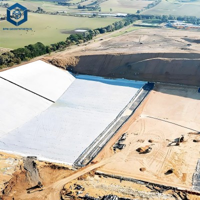
Landfill base liner (flat, 10,000 m²): Smooth HDPE, dual-track fusion welding. Subgrade: 200mm sand cushion + geotextile. Deployment: 2 crews of 4, 1,200 m²/day. Seaming: 3 welders, 400 linear m/day. Testing: 100% air channel, destructive samples every 150m.
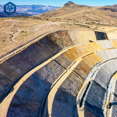
Landfill side slope (3H:1V, 5,000 m²): Textured HDPE, dual-track fusion with conditioners. Subgrade: proof-rolled, anchored at top. Deployment: winch-assisted, 500 m²/day. Seaming: uphill direction, 200 linear m/day. Testing: air channel (pump uphill).
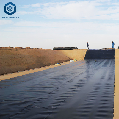
Pond liner (gentle slope, 20,000 m²): Smooth or LLDPE, dual-track fusion. Subgrade: smooth-rolled, no cushion needed if free of rocks. Deployment: 1,500 m²/day. Seaming: 500 linear m/day. Testing: vacuum box for single-track seams.
Mining heap leach pad (large area, 50,000+ m²): Textured HDPE, automated welding for long straight seams. Prefabricated panels (20m x 20m) reduce field seaming. Deployment: 2,000 m²/day with large crews.
Common Industry Problems and Engineering Solutions
Problem 1 – Cold weld (peel test adhesion failure, smooth interface)
Root cause: Wedge temperature too low (<400°c) or="" speed="" too="" fast="">3 m/min). Solution: Increase temperature by 10-20°C, reduce speed by 0.3-0.5 m/min. Re-trial seam before production.
Problem 2 – Burn-through (visible thinning, holes in seam)
Root cause: Temperature too high (>500°C) or speed too slow (<1.2 m/min). Solution: Reduce temperature by 20-30°C, increase speed. Cut out and replace damaged section (cannot repair).
Problem 3 – Punctures from subgrade stones (visible holes, leaks)
Root cause: Angular stones >20mm not removed. Subgrade not proof-rolled. Solution: Reject subgrade before deployment. After puncture found, cut out damaged area (minimum 300mm diameter circle), patch with extrusion weld.
Problem 4 – Air channel test fails (pressure decay >20% in 5 minutes)
Root cause: Pinhole, incomplete fusion, or debris in seam. Use soapy water to locate leak. Mark and cut out failed section (minimum 300mm beyond leak), re-weld. For dual-track, repair with extrusion welder.
Risk Factors and Prevention Strategies
| Installation Method | Seam strength (parent %) | Production speed (m²/day/crew) | Quality control complexity | Best application |
|---|---|---|---|---|
| Dual-track fusion (hot wedge) | 90-100% | 800-1,500 (flat), 400-800 (slope) | Moderate (temperature, speed, pressure) | Primary seams, landfills, ponds |
| Extrusion welding (handheld) | 70-85% | 200-400 (repairs only) | High (operator skill dependent) | Repairs, pipe boots, penetrations |
| Single-track fusion (small wedge) | 85-95% | 600-1,000 | Moderate | Tight radius curves, small overlaps |
| Adhesive bonding (not recommended for HDPE) | 30-50% | 500-800 | Low | Temporary applications only |
| Risk Factor | Consequence | Prevention Strategy (Spec Clause) |
|---|---|---|
| Subgrade puncture from rocks | Angular stone penetrates liner under load .="Subgrade shall be smooth-rolled, maximum stone size 20mm. Geotextile cushion (200 g/m²) required for angular subgrade. Proof roll with loaded truck before deployment." | |
| Cold weld (insufficient heat) | Temperature too low or speed too fast .="Welding parameters: temperature 440-460°C for 1.5mm HDPE, speed 1.8-2.2 m/min. Calibrate contact pyrometer each shift." |
Burn-through (excessive heat)Temperature too high or speed too slow .="Monitor temperature display continuously. If burn-through occurs, cut out damaged section (300mm radius) and replace."Untrained weldersNon-certified operators produce inconsistent seams .="All welding operators shall hold current IAGI or NACE certification for HDPE geomembrane welding. Certification cards available for inspection."No non-destructive testingUndetected seam leaks cause containment failure .="100% of dual-track seams shall be air channel tested at 30 psi for 5 minutes. Extrusion welds vacuum box tested. Destructive samples every 150m per ASTM D6392."
Procurement Guide: How to Select an HDPE Installation Contractor
Verify IAGI or NACE certification – Require proof of current company certification and individual welder cards. Minimum 3 certified welders for crew.
Review past project references – Request 5 similar-scale projects (landfill, mining, pond). Contact owners for performance feedback (leaks, schedule, CQA reports).
Check equipment inventory – Fusion welders (dual-track), extrusion welders, vacuum testers, air channel kits. Calibration logs for temperature sensors (last 30 days).
Require pre-installation meeting – Hold a pre-construction meeting covering subgrade acceptance, welding parameter trials, testing protocols, and CQA hold points.
Demand trial seam panel – Before production welding, contractor shall weld 10m trial seam. Destructive test per ASTM D6392 – must pass before proceeding.
Specify CQA hold points – Subgrade acceptance, panel deployment inspection, welding parameter verification, non-destructive testing, destructive sampling, repair documentation.
Include warranty clause – "Contractor warrants all seams for 5 years against defects. Any leak attributed to seam failure shall be repaired at contractor's cost."
Engineering Case Study: Landfill Base – Installation Error and Corrective Action
Project: 15-acre MSW landfill base liner, 1.5mm smooth HDPE. Certified installation crew, dual-track fusion welding.
Problem detected during CQA: Air channel test on 8 of 40 seams (20%) showed pressure decay >20% in 5 minutes. Destructive samples from same seams failed peel test (peel strength 15 N/cm vs required 31 N/cm). Failure mode: adhesive failure (smooth surface, no fiber tear).
Root cause investigation: Welding machine temperature sensor drifted. Set point 450°C, but contact pyrometer measured actual wedge temperature 385°C. Operator had not calibrated machine at shift start (violation of spec). Speed was 2.2 m/min – too fast for 385°C.
Corrective action: Recalibrated temperature sensor. Adjusted set point to 470°C to achieve actual 445°C. Reduced speed to 1.8 m/min. Re-tested trial seam – passed peel (45 N/cm, cohesive fiber tear).
Remediation: Cut out 380 linear meters of failed seams (12% of total). Re-welded with corrected parameters. Re-tested – all passed. Added labor: 3 days x 4 welders = 96 hours ($12,000). Lost production: 2 days ($20,000).
Measured outcome: The how to install hdpe geomembrane step by step guide lesson: temperature calibration at shift start is mandatory. A $500 contact pyrometer would have prevented $32,000 in remediation. The project now requires daily calibration log signed by CQA inspector before any welding.
FAQ – How to Install HDPE Geomembrane Step by Step Guide
Request Technical Support or Quotation
We provide installation QA/QC plans, contractor prequalification, and CQA inspection services for HDPE geomembrane projects worldwide.
✔ Request quotation (project area, liner type, slope conditions, certification requirements)
✔ Download 30-page HDPE installation QA/QC manual (with checklists and hold-point forms)
✔ Contact installation engineer (IAGI certified, 18 years experience)
[Reach our engineering team via project inquiry form]
About the Author
This technical guide was prepared by the senior geosynthetic engineering group at our firm, a B2B consultancy specializing in HDPE geomembrane installation QA/QC, contractor qualification, and forensic failure analysis. Lead engineer: 22 years in HDPE installation management (over 12 million m² installed), 18 years in CQA supervision, and IAGI certified master trainer. Every installation procedure, test parameter, and case study derives from ASTM/GRI standards and field project experience. No generic advice – engineering-grade protocols for CQA engineers and installation contractors.