Best Travel Speed for Wedge Welding HDPE Liner
In the installation of high-density polyethylene geomembranes, the welding process is the single most critical quality control point. Determining the best travel speed for wedge welding HDPE liner is not a matter of guesswork; it is a precise engineering calculation that balances heat input, pressure, and dwell time to achieve a homogenous fusion zone. This guide provides a detailed technical analysis of travel speed optimization, covering the physics of heat transfer, material-specific parameters, field validation methods, and the procurement considerations that impact welding productivity and seam integrity. For site engineers, quality assurance managers, and EPC contractors, mastering this parameter is essential for achieving consistent, code-compliant seams in landfill, mining, and water containment projects.
What is the Best Travel Speed for Wedge Welding HDPE Liner
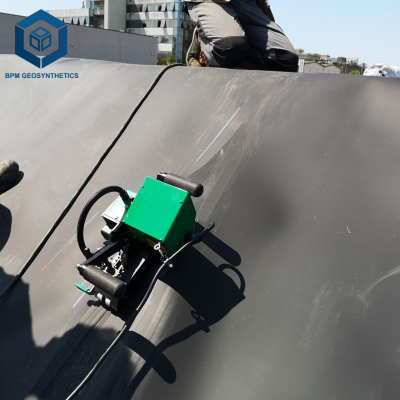
The best travel speed for wedge welding HDPE liner is the optimal velocity at which an automatic hot wedge welding machine traverses the overlap zone, delivering sufficient thermal energy to melt the polymer interface while ensuring adequate consolidation under pressure. This speed is typically expressed in meters per minute (m/min) and is inversely proportional to the material thickness—thicker liners require slower speeds to allow heat to penetrate the entire cross-section. In the engineering context, travel speed is one of three interdependent welding parameters, alongside temperature and pressure, that collectively define the weld's quality. For procurement and project management, establishing the correct travel speed is critical for balancing production rates with the rigorous seam strength requirements mandated by ASTM D6392 and GRI GM19 standards.
Technical Specifications and Speed Parameters
Determining the best travel speed for wedge welding HDPE liner requires a thorough understanding of the material's thermal properties and the machine's capabilities. The following table outlines the recommended speed ranges and their engineering significance.
| HDPE Thickness (mm) | Recommended Speed Range (m/min) | Typical Wedge Temperature (°C) | Engineering Importance |
|---|---|---|---|
| 0.75 – 1.0 | 3.5 – 5.0 | 370 – 400 | Thinner sheets heat rapidly; higher speeds prevent overheating and burn-through. |
| 1.0 – 1.5 | 3.0 – 4.5 | 380 – 410 | Balanced heat input for standard geomembrane applications. Most common range. |
| 1.5 – 2.0 | 2.0 – 3.5 | 400 – 430 | Slower speed ensures full-thickness melting for high-strength barrier requirements. |
| 2.0 – 2.5 | 1.5 – 2.5 | 420 – 450 | Requires precise speed control to avoid cold welds; used in heavy-duty mining and landfill base liners. |
| 2.5 – 3.0 | 1.0 – 1.8 | 430 – 460 | Slowest speeds; thermal management is critical to prevent polymer degradation while ensuring fusion. |
Factors Influencing the Optimal Travel Speed
While the above table provides a baseline, the best travel speed for wedge welding HDPE liner is influenced by several variables that must be assessed on-site. The following table details these factors and their impact on speed selection.
| Factor | Impact on Speed | Engineering Consideration |
|---|---|---|
| Ambient Temperature | Cold conditions require slower speeds; hot conditions allow faster speeds | Heat dissipation rate changes; adjust speed to maintain consistent melt zone temperature. |
| Material Color (Carbon Black Content) | Higher carbon black content requires slightly slower speeds | Carbon black absorbs heat differently; adjust speed for UV-stabilized vs. non-stabilized liners. |
| Surface Contamination | Dust or moisture necessitates slower speeds for cleaning and drying | Contamination reduces thermal transfer; pre-cleaning may allow speed recovery. |
| Machine Condition (Wedge Oxidation) | Oxidized wedge requires slower speeds | Reduced thermal efficiency; plan for wedge replacement or speed adjustment. |
| Subgrade Evenness | Uneven surfaces cause speed fluctuations | Use a machine with automatic speed stabilization or reduce speed for manual control. |
Material Structure and Composition of HDPE Liner
The best travel speed for wedge welding HDPE liner is intrinsically linked to the material's internal structure and additives. Understanding this composition is essential for optimizing welding parameters.
| Layer / Component | Material | Impact on Welding Speed |
|---|---|---|
| Base Polymer | HDPE resin (0.940 – 0.960 g/cm³) | Higher density requires slower speeds due to higher thermal conductivity and melt temperature. |
| Carbon Black (UV Stabilizer) | 2.0 – 3.0% by weight | Absorbs infrared radiation, increasing heat uptake. May require speed reduction of 0.2-0.5 m/min. |
| Antioxidants | Hindered phenol stabilizers | No direct impact on speed but affect long-term thermal stability; slower speeds reduce thermal stress. |
| Surface Texture | Embossed or smooth finish | Textured surfaces may require slightly slower speeds to ensure complete melting in the valley areas. |
Engineering Methodology for Speed Determination
Determining the best travel speed for wedge welding HDPE liner on a project site follows a systematic engineering approach rather than relying on a fixed number. The following steps are standard practice for QA/QC protocols.
Material Verification: Confirm the liner's thickness and resin grade from the manufacturer's certificate. This defines the starting point for speed selection.
Initial Test Strip Welding: At the start of each shift, weld a 300mm test strip at the estimated speed, temperature, and pressure. Cut the strip and perform a peel test (ASTM D6392) to assess fusion quality.
Speed Adjustment: If the peel test shows incomplete fusion (adhesive failure), reduce speed by 0.2-0.3 m/min. If the bead is burnt or shows signs of degradation (cohesive failure with discoloration), increase speed.
Validation: Continue test strip welding until three consecutive strips pass the peel and shear tests. Document the final speed, temperature, and pressure as the approved parameters for that shift.
Re-validation: Re-validate the speed whenever there is a material change, a machine maintenance event, or an ambient temperature change greater than 10°C from the original validation.
Performance Comparison: Optimized Speed vs. Fixed Speed Welding
For procurement and operations managers, the difference between using the best travel speed for wedge welding HDPE liner and a fixed, unverified speed is significant in terms of quality and cost.
| Approach | Seam Quality | Productivity (m/hour) | Rework Rate | Typical Applications |
|---|---|---|---|---|
| Optimized Speed (Daily Calibration) | High (Consistent pass rate > 98%) | Optimal (Balanced for material) | Low (< 2%) | EPC projects, mining, large landfills |
| Fixed Speed (No Daily Adjustment) | Variable (May pass or fail) | Potentially faster but higher rework | High (10-15% or more) | Small projects, non-critical applications |
| Speed Too High (Under-welding) | Poor (Adhesive failure, low peel strength) | High initial, but rework negates gains | Very High (30%+) | Projects with time pressure, poor QA |
| Speed Too Low (Over-welding) | Poor (Burnt bead, degraded polymer) | Low (Reduces productivity) | High (Material waste from burning) | Inexperienced operators |
Industrial Applications and Speed Considerations
The best travel speed for wedge welding HDPE liner must be contextualized for each application environment, as different sectors impose unique constraints.
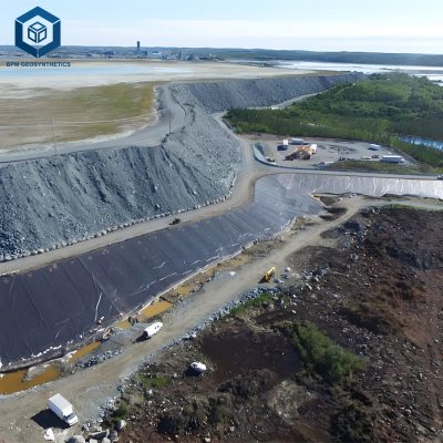
Mining Heap Leach Pads: Typically use 1.5-2.0mm HDPE. Speeds of 2.5-3.5 m/min are common. However, high-altitude sites with low ambient temperatures may require speeds 10-15% slower than standard.
Landfill Base Liners: Often use 2.0mm textured HDPE. Speeds of 2.0-3.0 m/min are standard, but textured surfaces may require a 0.2 m/min reduction to ensure valley penetration.
Landfill Caps (Exposed): Thinner liners (1.0-1.5mm) allow speeds of 3.5-4.5 m/min. However, UV exposure during installation necessitates faster speeds to minimize heat soak.
Water Reservoirs: Often use 1.5mm smooth HDPE. Speeds of 3.0-4.0 m/min are typical, with a focus on consistent speed across large panel sizes.
Tunnel Waterproofing: Tight spaces and variable surfaces may require manual speed control. Often, speeds are reduced to 1.5-2.0 m/min to ensure safety and quality in constrained environments.
Common Industry Problems and Engineering Solutions
Even with a calculated best travel speed for wedge welding HDPE liner, field issues can arise. The following are four common problems related to speed and their engineering solutions.
Problem: Inconsistent bead width across the weld length.
Root Cause: The operator is not maintaining a constant speed due to fatigue or terrain changes.
Solution: Use a machine with a closed-loop speed control that maintains constant travel speed regardless of load. Alternatively, provide operator training on pace consistency.Problem: Peel test failure at the start of the weld (cold start).
Root Cause: The wedge has not reached its stable operating temperature, or the machine started at full speed before the material was properly heated.
Solution: Implement a "pre-heat" protocol: run the machine on a scrap piece for 30 seconds before starting the production seam, or reduce speed by 50% for the first 100mm of the weld.Problem: Intermittent burnt sections in an otherwise good weld.
Root Cause: The speed control system is experiencing hysteresis or the machine is slowing down on slight inclines.
Solution: Calibrate the speed controller. Use a machine with a more sophisticated drive system (e.g., brushless DC motor with encoder feedback).Problem: Poor fusion on textured liners despite correct speed for smooth liners.
Root Cause: The textured surface creates air gaps that insulate the polymer, requiring more heat input (slower speed) to achieve fusion.
Solution: Reduce speed by 10-15% for textured liners compared to smooth liners of the same thickness. Verify with test strips.
Risk Factors and Prevention Strategies
Optimizing the best travel speed for wedge welding HDPE liner requires a proactive approach to risk management. The following strategies are essential for preventing speed-related failures.
Risk: Improper Speed Selection. Prevention: Always validate speed with test strips at the start of each shift and after any environmental or material change.
Risk: Material Mismatch (Unexpected Thickness Variation). Prevention: Measure the actual thickness of the liner on-site using a micrometer. Adjust speed according to the measured thickness, not the nominal value.
Risk: Environmental Exposure (Rapid Temperature Change). Prevention: Monitor ambient temperature and wind speed. Increase speed by 5-10% in hot, calm conditions; decrease speed in cold, windy conditions.
Risk: Subfloor or Foundation Issues (Uneven Support). Prevention: Ensure the subgrade is smooth and compacted. Uneven surfaces cause the machine to rock, altering the effective speed.
Procurement Guide: Choosing Equipment for Speed Optimization
Procuring equipment that supports the best travel speed for wedge welding HDPE liner is a strategic investment. The following checklist is designed for B2B buyers.
Traffic Load Evaluation: For high-volume projects, choose machines with digital speed displays and closed-loop control for consistent speed.
Specification Verification: Verify that the machine's speed range (e.g., 0.5 – 6.0 m/min) covers the entire range of liner thicknesses you will encounter.
Certifications: Prefer equipment with CE or UL certification, which often implies more robust speed control electronics.
Supplier Capability: Evaluate the supplier's ability to provide technical support for speed calibration and troubleshooting.
Quality Control: Demand a factory speed calibration certificate and test the machine's speed accuracy on-site with a tachometer.
Sample Testing: Request a machine for a trial period to evaluate its speed stability across different liner types.
Warranty Evaluation: Review the warranty for the drive motor and speed controller—typically 24 months for high-quality equipment.
Engineering Case Study: Speed Optimization on a Large-Scale Landfill Project
Project Type: Municipal Solid Waste Landfill Expansion
Location: Northeastern United States
Project Size: 35 hectares of 2.0mm textured HDPE liner
Product Specification: Automatic wedge welding machines with digital speed control, target speed range 2.0-3.0 m/min.
Challenge: The project was experiencing a 12% first-pass seam rejection rate, primarily due to inconsistent bead formation and peel test failures. The site engineer suspected that the speed setting was not being adjusted for daily temperature variations.
Implementation: A systematic speed optimization protocol was implemented. Each morning, a test strip was welded at the current machine settings and tested. The speed was adjusted based on the peel test results, and the ambient temperature and liner temperature were logged. A "speed-temperature compensation chart" was developed for the site, correlating ambient temperature with required speed adjustments.
Results and Benefits: After two weeks of implementation, the rejection rate dropped to 2.5%. The project was completed on schedule, with significant savings in rework materials and labor. The speed optimization protocol became a standard operating procedure for the contractor's future projects, demonstrating that the best travel speed for wedge welding HDPE liner is a dynamic parameter that must be actively managed, not a fixed number.
FAQ Section
What is the typical travel speed for welding 1.5mm HDPE liner?
How does ambient temperature affect welding speed?
Is travel speed the same for smooth and textured HDPE liners?
What is the relationship between travel speed and weld temperature?
How do I know if my travel speed is too fast?
How do I know if my travel speed is too slow?
How often should the travel speed be validated on a project?
Can a machine with manual speed control achieve optimal results?
What is the impact of wind on travel speed selection?
Should I use the same speed for extrusion welding as for wedge welding?
Request Technical Support or Quotation
Optimizing the best travel speed for wedge welding HDPE liner on your project requires technical expertise and reliable equipment. Our engineering team provides site-specific guidance.
Request a detailed speed optimization protocol for your project.
Request sample welding trials with speed calibration support.
Download technical data on speed control systems and calibration tools.
Request a consultation on QA/QC procedures for seam welding.
About the Author
This guide was developed by a team of senior engineers and B2B technical consultants with over 15 years of experience in geosynthetics installation, welding equipment design, and EPC project management. Our expertise spans manufacturing, field operations, and quality assurance across the mining, waste management, and infrastructure sectors.